Notes1
TOPIC 1 – APPLICATIONS OF VECTORS
TOPIC 2 – FRICTION
TOPIC 3 – LIGHT
TOPIC 4 – OPTICAL INSTRUMENTS
TOPIC 5 – THERMAL EXPANSION
TOPIC 6 – TRANSFER OF THERMAL ENERGY
TOPIC 7 – MEASUREMENT OF THERMAL ENERGY
TOPIC 8 – VAPOUR AND HUMIDITY
TOPIC 9 – THERMAL CURRENT ELECTRICITY
IMPORTANCE OF PHYSICS IN OUR DAILY LIFE – PART 3
14.
Physics is a basic tool by which the doctor understands most drug reactions. A bachelor of
medicine and bachelor of surgery (MBBS) is one of the best degrees to become a
doctor. If you want to become a doctor, you need to study physics.
15.
A Wide Range of Career Opportunities
If
you’re wondering about what kind of jobs there are with a physics degree,
the great answer is that there are so many to choose from!
Although
a physics degree is naturally highly embedded in science, physics graduates
don’t necessarily have to go into jobs that are scientific in nature,
and you certainly don’t have to become a scientist or physicist if
you don’t want to.
Of
course, if you have your heart set on becoming an astrophysicist or a
laboratory technician, then you can naturally pursue those avenues, but it’s
also important to note that there are other career paths out there for
physics graduates.
For
example, physics graduates may find themselves working in a variety
of different sectors, such as: Government or the public sector, Business
and finance or Technology.
16.
Physics Clears the Air
Physics
is used in environmental science to both detect problems and to build systems
that are better for the environment with technologies such as solar power and
plasma physics.
17.
Physics Designs the Future
Research
in materials physics has led to many innovations in the substances from which
products are made. One now-common material is Teflon Other substances are now
used to make many items from sports equipment to earthquake-resistant
buildings.
18.
A physics student develops is a sense of wonder about how things work. We are
living in a technologically advanced age in which the average person relies on
technology without understanding how that technology works. How many of us have
looked at a DVD disc, and wondered how it can contain an entire film? Who has
held an ipod and thought about how so many songs can be squeezed into a tiny
space? Physics teaches us a method of systematic thinking and also the theories
necessary to allow us to once again understand how the things we rely on
actually work.
………..
LIGHT
Light is a form of energy which controls the sense of vision. We are able to see things because of the light coming from them.
Reflection of Light from Curved Mirrors
Difference between Concave and Convex Mirrors
Distinguish between concave and convex mirrors
Concave mirror is a spherical mirror whose reflecting surface is curved inwards. A Good example is the driving mirror of a car.
Convex mirror is a spherical mirror whose reflective surface is curved outwards. A good example of a convex mirror is a shaving mirror.
General demonstrations of convex and concave mirrors (curved mirrors:
The Terms Principle, Axis, Pole, Principle Focus and Radius of Curvature as Applied to Curved Mirrors
Explain the terms principle, axis, pole, principle focus and radius of curvature as applied to curved mirrors
Terms used in studying curved mirrors
- Centre of curvature (C):the centre of the sphere of which a mirror is a part of.
- Radius of curvature (r): the radius of sphere of which a mirror is a part of. Radius of curvature is double the focal length. That is r=f/2.
- Pole (P): the central point of the reflecting surface of spherical mirror (curved or convex mirror).
- Principal axis:the straight line joining the centre of curvature (C) and the pole (P).
- Principal focus (F):the point on the principal axis where light rays tend to intersect after being reflected. This point is between centre of curvature and the pole. In concave mirror, parallel rays to the principal axis meet at the principal focus after reflection. In convex mirror, parallel rays to the principal axis appear to originate from the principal focus behind the mirror after reflection.
- Focal length (f):the distance from the pole of the mirror to the principal focus. Focal length is half the radius of curvature.
The Images Formed by a Curved Mirror
Locate the images formed by a curved mirror
Case (1)
When a beam of light parallel and very close to the principal axis CL, is reflected from a concave mirror, it converges to a point F, on the principal axis called the principal focus.
Case 2
When a ray passes through the principal focus, F, it is reflected parallel to the principal axis.
Case 3
When a ray passes through the centre of curvature, C, which therefore strikes the mirror at normal incidence, it is reflected back along its original path.
Note: Concave mirrors have a real focus because light passes through the focus.
The formation of images by concave mirror tends to change as the position of object changes.
Case 1: Image (I) formed by a concave mirror when the object is beyond C.
Properties of images formed:
- The image is between C and F
- The image is smaller than the object
- The image is inverted (upside down)
- The image is real
Case 2: The object is placed at C
Properties of image
- The image is formed at C
- The image has the same size as object
- The image is inverted (upside down)
- The image is real.
Case 3: The object is placed between C and F
Properties of image formed
- The image is real
- The image is large than object
- The image is formed beyond C
- The image is inverted (upside down)
Case 4:The object is placed at F
Properties of image:
- The image is formed at infinity (x)
- The image is formed beyond C
- The image is large than object
- The image is Real
Case 5:The object is placed between F and P.
Properties of image formed:
- The image is virtual
- The images is upright
- The image is formed behind the mirror
- The image is large than the object
Formation of images in a convex mirror:
Obviously, there is only one kind of image formed when an object is placed at any position.
Properties of image formed by convex mirror:
- The image is virtual
- The image is upright
- The image is smaller than object (diminished)
- The image is formed behind the mirror.
Note: We see images of ourselves and other things through curved mirrors when they are formed behind the mirrors, virtual and upright. For the concave mirrors, images are magnified but for convex mirrors, images are diminished. All real images cannot be seen through the mirrors because they are formed in front of the mirror.
The Mirror formula
This shows the relationship between the distance of the object from the mirror U, distance of the image from the mirror V and the focal length f.
To avoid confusions the formula is used by considering a sign convention known as ‘positive-is-real convention’. In Positive-is -real sign convention the following are to be considered before applying the values into the equations;
- Real images are given a positive ‘+’ sign.
- Virtual images are given a negative ‘-‘ sign.
- Distances of real objects and images are given positive ‘+’sign.
- Distances of virtual images are given negative ‘-‘ sign.
- A real focal length is given a positive ‘+’ sign.
- A virtual focal length is given a negative ‘-‘ sign.
Magnification
Magnification is the ratio of the image distance to the object distance. Magnification is a unit less quantity which shows how much the image is larger or smaller to the object.
In this case, magnification is also defined as the ratio of the height of the image to the height of the object.
Example 1
An object 2cm long is erected 8cm infront of a concave mirror of radius of curvature 10cm. By using a scale drawing, determine the position, size and nature of image formed.
Data given
- Height of object, Ho = 2cm
- Object distance, U= 8cm
- Radius of curvature, r = 10cm
- Focal length,f =8cm
- Choose suitable scale.
- Say 1cm represents 5cm
From this scale then
- Height of object, Ho = 2cm
- Object distance, U= 2cm
- Focal length, F = 2.5cm
Thus,
Image distance, V = X
Image Height, H1=Y
The Focal Length of a Concave Mirror
Determine practically the focal length of a concave mirror
Focal length (f) is the distance between the principal focus and the pole.
Convex and Concave Mirrors in Daily Life
Use Convex and concave mirrors in daily life
Curved mirrors are used as:
- Driving mirrors
- Shaving mirrors
- Reflectors
Question Time 1
Why is convex mirror used as driving mirror?
The convex mirror is used as driving mirror because it provides the wider field of view.
Question Time 2
Why concave mirror used as shaving mirror?
Concave mirrors are used as shaving mirrors because they form an enlarged image when held close up.
Refraction of Light
The Concept of Refraction of Light
Explain the concept of refraction of light
Refraction of light refers to the bending of light as it passes through two different media. This bending takes place because the speed of light tends to change when travelling from one medium to another. For refraction to occur the two media must have different densities.
Figure showing refraction of light as it passes from air to glass.
The Angle of Incidence and Angle of Refraction
Measure the angle of incidence and angle of refraction
The angle of incidence (i)is the angle between the incident ray of light and the normal at the point of incidence.
The angle of Refraction (r)is the angle between the refracted ray and the normal at the point of incidence.
The Laws of Refraction
State the laws of refraction
First law of refraction
The First Law of refraction states that “the incident ray, the refracted ray and the normal at the point of incident are located in the same plane.”
Second law of refraction
Second Law of refraction states that “when a light ray passes from one medium into another medium, the angle of incidence (i) and corresponding angle of refraction( r) are such that the ratio of sine of the angle of incidence to the sine of the angle of refraction (sini/sinr) is a constant value called the refractive index.”
Note: The Second Law of Refraction is called Snell’s Law in honour of a Dutch scientist named Snell (1591 – 1626) who first described it.
The Refraction Index of a Material
Determine the refraction index of a material
Refractive index (n) is the ratio of the sine of the angle of incidence to the sine of the angle of refraction.
Refractive index (n) is the ratio of the velocity of light in first medium to the velocity of light in the other medium.
Refractive index, n is the constant number which expresses how many times or to what extent a light ray bends when passing through different medium.
Absolute refractive index (na) is the refractive index between vacuum or air and any other medium.
The refractive indices between air and some common media is given below:
| Medium | Refractive index (n) |
| Diamond | 2.417 |
| Ethanol | 1.360 |
| Glass (Crown) | 1.520 |
| Quartz | 1.553 |
| Water (at 20ºC0 | 1.333 |
| Air (at stp) | 1.00029 |
Example 2
The refractive index for light passing from air to water is equal to 1.333 find the refractive index for light travelling from water to air.
Data given:
Refractive index anw of air to water = 1.333
Required: To find refractive index from water to air
Since
anw = 1.333
wna = (1/anw)
= (i/1.333)
: wna = 0.75
Real and Apparent Depth
Real depthis the actual height measured without taking account any refraction of light
Apparent depth is the virtual height measured when viewed by observer.
Real and apparent depth can be seen when viewing a spoon immersed in a water contained in a glass. When the spoon is viewed from the top of the glass, it will be seen bending.
The bottom of the river is seen to be lifted upwards though the real level of the bottom is deep below. This lifted bottom is known as the apparent depth.
The Concept of Critical Angle and Total Internal Reflection of Light
Explain the concept of critical angle and total internal reflection of light
Critical angle
Critical angleis the angle of incidence (i) for which the angle of refraction (r) is equal to 90º . It is obtained when light rays moves from a dense medium to a less dense medium.
Total Internal Refraction
This occurs when a light ray from a less dense medium is reflected into the denser medium at the boundary separating the two media.
Conditions for total internal reflection to occur include the following:
- Light must be travelling from a more dense to less dense medium.
- Light must incident at the boundary at an angle greater than the critical angle (C).
Optical fibres
These are very thin tubes of plastic or glass and because they are so thin they can bend without breaking, so they can carry light around the corners.
Uses of optical fibres
- Used in telecommunications to carry telephone calls over vast distance, without loss of intensity and without interference.
- Used in endoscope to view inside a patient body for example inside stomach. Light is carried into the stomach through a bunch of fibres and is reflected into small camera, which then displays a picture on a screen.
The Occurance of Mirage
Explain the occurrence of mirage
This is the phenomenon in which an object appears to be at an incorrect position due to the bending of light rays from the object.
Mirages occur during hot days.
Refraction of Light by Rectangular Prism
The Passage of Light through a Triangular Prism
Trace the passage of light through a triangular prism
Light rays are deviated after passing through the glass prism. Deviation is used to explain how light rays bend after entering the face of the glass prism.
Deviation of light in a prism is the changing in direction of the incident ray when it enters/hits a triangular glass prism.
The angle of deviation D is the amount by which the ray bent away from its original direction.
Minimum Deviation (d)
As the angle of incidence is increased, angle of deviation ‘D’ decreases and reaches minimum value ‘d’. If the angle of incidence is further increased, the angle of deviation is increased. The minimum deviation is important in the calculation of the refractive index of a glass prism using the following formula;
Angle of prism is the angle between two refracting surfaces of the glass prism.
The Dispersion of White Light
Demonstrate the dispersion of white light
Dispersion of light is the splitting up of light beam (white light) into its seven components of colour by a prism.
Spectrum is the patch or band of colours which comprise / constitute seven component of white light.
Pure section is the patch or band of colours in which the colours are clearly separated.
In order to produce pure spectrum then we must use two converging lenses (convex lenses).
When colours of spectrum are combined, they form white light.
In order to combine colours of the spectrum, we need two triangular glass prisms and one lens.
Impure spectrum:the band/patch of colours which overlap and are not seen clearly.
The rainbow:a bow-shaped spectrum of seven colours of white light formed when white light undergoes dispersion within the rain drops because water is denser than air, so has a large refractive index.
Activity 1
A rainbow can be demonstrated as follows:
Spray some water into the air in a direction opposite to that of the sun.
Look at the water shower while you face away from the sun. You will see the colour of the spectrum of white light in the falling drops of water. The spectrum so formed hasthe shape like a bow. So it is called rainbow.
There are two main types of rainbow:
- Primary rainbow
- Secondary rainbow
Primary rainbow
This is formed when light undergoes one or single total internal reflection in the water droplets. In this type of the rainbow the violet colour is on the inside of the bow while the red colour is on the outside.
Secondary rainbow
Secondary rainbow takes place when the sun rays undergo two internal reflections in the raindrops. Its intensity is fainter than the primary rainbow and it has violet colour at the top and red at the bottom.
The Angles of Deviation and Minimum Deviation
Determine the angles of deviation and minimum deviation
The refractive index of the prism can be calculated by using the prism angle ‘A’ and the angle of minimum deviation ‘d’. The angle of minimum deviation can be obtained graphically by drawing a graph of the angle of deviation ‘D’ against the angle of incidence. It is known that as the angle of incidence is increased, angle of deviation ‘D’ decreases and reaches minimum value ‘d’. If the angle of incidence is further increased, the angle of deviation is increased.
The total angle of deviation ‘D’ is the angle between the direction orf the incident ray and the emergent ray.
A Simple Prism Binocular
Construct a simple prism binocular
Simple prism binocular
Colours of Light
The Component of White Light
Explain the component of white light
There are two types of colour of light
- Primary colour of light
- Secondary colour of light
Primary colour of light
These are basic (fundamental ) Colour of light to which the eye is most sensitive.Primary Colour of light Include the following
- Red
- Green
- Blue
Secondary colours of light
These are colour of light obtained after mixing primary colours of light
Colour mixing by Addition
This is the process of combining primary colours of light without loss of any colour to form secondary colours of light.
| Primary color | Secondary color | |
| Red + Blue | Magenta | |
| Red + Green | Yellow | |
| Blue + Green | Cyan |
Colours of White Light
Recombine colours of white light
When all primary lights ( Red , Blue and Green) combine WHITE LIGHT is formed.
Complementary colours of light: These are the colours which produce white light when combined.
- Red + Blue+ Green – White light
- Red + Cyan – White light
- Blue + Yellow – White light
- Green + Magenta – White light
The Appearances of Coloured Object under White Light
Explain the appearances of coloured object under white light
There are two types of coloured paints ( pigments) which Include the following
- Primary coloured pigment (paints)
- Secondary coloured pigment (paints)
Primary, Secondary and Complementary Colours of Light
Identify primary, secondary and complementary colours of light
Primary Coloured pigments
These are basic coloured pigments which form secondary coloured pigment when combined.
The primary coloured pigments include:Yellow, Cyan and Magenta
Secondary colour pigments
These are coloured pigments which are formed when two primary colours combine, whichis always accompanied with the removal of other colours.
Difference between Additive and Subtractive Combination of Colours
Distinguish between additive and subtractive combination of colours
Colour Mixing by Substration
Is the process of mixing two primary coloured paints ( pigments) to form secondary colour white.
Example 3
- Magenta + Cyan
- Magenta = ( Blue) + ( Red)
- Cyan = (Blue) + (green)
The colour which is common to Blue will appear while red and green disappear.
Magenta + Cyan = Blue
Example 4
- Magenta + yellow
- Magenta = (Blue) + (Red)
- Yellow = (Green) + (Red)
The colour which is common to both red will appear while blue and green will disappear.
Hence
Magenta + Yellow = Red
Example 5
- Cyan + yellow
- Cyan = (Blue) + (Green)
- Yellow = (Red) + (Green)
The colour which is common to both green will appearwhile Blue and Red will disappear
Hence
Cyan + Yellow = Green
Refraction of Light by Lenses
Difference between Convex and Concave Lenses
Distinguish between convex and concave lenses
A lens is a transparent medium bounded by two surfaces of regular shape. There are two major categories of lenses which include:
- Convex lens-they are thicker at the middle than at the edges.
- Concave lens– they are thinner at the middle than at the edges.
The Terms Focal Length, Principle Focus, Principle Axis and Optical Centre as Applied to Lenses
Explain the terms focal length, principle focus, principle axis and optical centre as applied to lenses
Optical center is a geometric center of a lens.
Center of curvatureis the center of the sphere in which a lens is a part.
Principal axisis an imaginary line which passes through the optical center of the lens at right angle to the lens.
Principle focusis a point through which all rays traveling close and parallel to the principal axis pass through.
The Focal Length of a Lens
Determine practically the focal length of a lens
Focal length (f) is a distance between between optical centre and the principal focus. It is important to note that the the principal focus is not the halfway between the optical centre and the centre of curvature in lenses as it is in mirrors. The plane through the principal focus which is at right angles with the principal axis is called the focal plane.
Example 6
An object is 2 cm high and placed 24cm from a convex lens. An image formed 72 cm. find the focal length of the lens.
Solution
i/f = 1/u + 1/v
1/f =1/24 + 1/72
1/f = 4/72
f = 18cm.
The Immage Formed by a Lens
Locate the image formed by a lens
Rays diagrams are normally used toillustratesthe formation of images by lenses.
- A ray parallel to the principal axis passes through or appears to diverge from the principal focus after refraction.
- A ray of light passing through the principal focus of a lens is refracted parallel to the principal axis of the lens.
- A ray of light through the optical center of the lens continues throughundeviated(Not change direction)
The position, Size and Nature of the Image formed by Lens
Determine the position, size and nature of the image formed by lens
The nature, position and size of the image formed by a lens depends on the position of the object in relation to the type of lens. For example in converging lens when the object is between the lens and principal focus the image will be formed at the same side as the object but further from the lens. It is virtual, erect, and magnified. The image by concave lens is erect, virtual and reduced.
Activity 2
- Take a convex lens. Find its approximate focal length in a way described in Activity 11.
- Draw five parallel straight lines, using chalk, on a long Table such that the distance between the successive lines is equal to the focal length of the lens.
- Place the lens on a lens stand. Place it on the central line such that the optical centre of the lens lies just over the line.
- The two lines on either side of the lens correspond to F and 2F of the lens respectively. Mark them with appropriate letters such as 2F1, F1, F2and 2F2, respectively.
- Place a burning candle, far beyond 2F1to the left. Obtain a clear sharp image on a screen on the opposite side of the lens.
- Note down the nature, position and relative size of the image.
- Repeat this Activity by placing object just behind 2F1, between F1and 2F1at F1, between F1and O. Note down and tabulate your observations.
The nature, position and relative size of the image formed by convex lens for various positions of the object is summarized in the table below:
| Position of the object | Position of the image | Relative size of the image | Nature of the image |
| At infinity | At focus F2 | Highly diminished, point-sized | Real and inverted |
| Beyond 2F1 | Between F2and 2F2 | Diminished | Real and inverted |
| At 2F1 | At 2F2 | Same size | Real and inverted |
| Between F1and 2F1 | Beyond 2F2 | Enlarged | Real and inverted |
| At focus F1 | At infinity | Infinitely large or highly enlarged | Real and inverted |
| Between focus F1and optical centre O | On the same side of the lens as the object | Enlarged | Virtual and erect |
Activity 3
- Take a concave lens. Place it on a lens stand.
- Place a burning candle on one side of the lens.
- Look through the lens from the other side and observe the image. Try to get the image on a screen, if possible. If not, observe the image directly through the lens.
- Note down the nature, relative size and approximate position of the image.
- Move the candle away from the lens. Note the change in the size of the image. What happens to the size of the image when the candle is placed too far away from the lens.
Nature, position and relative size of the image formed by a concave lens for various positions of the object
| Position of the object | Position of the image | Relative size of the image | Nature of the image |
| At infinity | At focus F1 | Highly diminished, point-sized | Virtual and erect |
| Between infinity and optical centre O of the lens | Between focus F1and optical centre O | Diminished | Virtual and erect |
The Magnification of the Lens Camera
Determine the magnification of the lens camera
As we have a formula for spherical mirrors, we also have formula for spherical lenses. This formula gives the relationship between object distance (u), image-distance (ν) and the focal length (f ). The lens formula is expressed as1/ν – 1/u = 1/f(8)
The lens formula given above is general and is valid in all situations for any spherical lens. Take proper care of the signs of different quantities, while putting numerical values for solving problems relating to lenses.
The magnification produced by a lens, similar to that for spherical mirrors, is defined as the ratio of the height of the image and the height of the object. It is represented by the letter m. If h is the height of the object and h′ is the height of the image given by a lens, then the magnification produced by the lens is given by,m = Height of the Image / Height of the object = h’ / h(9)
Magnification produced by a lens is also related to the object-distance u, and the image-distance ν. This relationship is given byMagnification (m ) = h’ / h = ν / u(10)
Example 7
A concave lens has focal length of 15 cm. At what distance should the object from the lens be placed so that it forms an image at 10 cm from the lens? Also, find the magnification produced by the lens.
Solution
A concave lens always forms a virtual, erect image on the same side of the object.
Image-distance v = –10 cm;
Focal length f = –15 cm;
Object-distance u = ?
Since, 1 /v – 1 / u = 1 / f
or, 1 / u = 1 / v – 1 / f
1 / u = 1 / -10 – 1 / (-15) = – 1 / 10 + 1 / 15
1 / u = (-3+2) / 30 = 1 / (-30)
or, u = – 30 cm.
Thus, the object-distance is 30 cm.
Magnification m = v/ u
m = -10 cm / -30 cm = 1 / 3 = +0.33
The positive sign shows that the image is erect and virtual. The image is one-third of the size of the object.
The Relationship between Focal Length (f) Object Distance (u) and Image Distance (v) as Applied to Lenses
Determine the relationship between focal length (f) object distance (u) and image distance (v) as applied to Lenses
The lens equation is given as 1/f =1/u + 1/v , if sign convection is used for u, v and f the equation applies to both converging and diverging lenses for all cases of object and image.
Example 8
An object is placed 12 cm from converging lens of focal length 18 cm. Find the position of the image.
Solution
Since the lens is converging f = +18 cm. 1/v = 1/18 -1/12, v = -36.
The image is virtual.
……………
FRICTION
Concept of Friction
The Concept of Friction
Explain the concept for friction
Friction is the force which opposes (resists) motion of the body. For example, a person will feel a certain resistance when pulling a block of wood resting on the table. The same kind of opposition can be felt when pushing a desk along a floor. That resistance (opposition) between two surfaces in contact is what we call friction.
Friction force is always in opposite direction to the applied force. This means, for a body to move, the applied force must exceed the friction force.
Friction force between two surface in contact exists only when there is relative motion between the two contacting surface.
The friction between two surfaces exists because of the nature of the surface of the bodies in contact. The roughness of the surface is due to the fact that every surface consists of peaks and valleys.
Demonstration
The peak and valleys on the surfaces of bodies may be due to a random arrangement of coarse particles, for example the surface of a grinding stones.
Smooth surfaces exert almost no friction.
When one body is pushed against another, the peaks of one surface have to rise up over the peaks of the other surface. Hence, opposition to motion or friction occurs when the force is acting to restore the bodies to their original position.
The Advantages and Disadvantages of Friction in Daily Life
Realize the advantages and disadvantages of friction in daily life
Advantages of Friction
Thefriction force has several advantages which includes the following:
- It helps in walking process. In this process, friction force stop us from slipping over.
- It helps cars to move on roads easily due to friction between car tyres and road.Therefore, makes the car stay on road. Most car tyres have deep dreads to increase friction between the tyres and the road surface.
- It helps in car braking system. Brakes rely on friction between the brake drum or pads and the wheels. In a bicycle, there are brake pads which clamp onto the wheel to slow it down.
Disadvantages of friction
Frictional force has several dis-advantages which include the following:
- Cause machinery to heat up and can cause wear and tear.
- Cause machinery to be less efficient.
- Cause machinery to produce noise.
Methods of Reducing Friction
Describe methods of reducing friction
The methods of reducing friction between surfaces include the following:
- Polishing: Polishing the surface reduces the roughness and hence reduces friction.
- Lubrication: It provides a layer of the smooth fluid or semi fluid between surfaces in contact so that they slide over each other smoothly.
- Use of ball-bearings or rollers: Rollers help to convert sliding friction into a milder form-rolling friction. Rolling friction is lesser than sliding friction.
- Streamlining: Fast cars, boats, planes etc., have a streamlined body. This is to allow air (or water in the case of boats) to easily flow by, without offering much resistance. Flying birds have streamlined bodies.
- Use of correct combination of surfaces in contact: Use of alloys on moving and sliding parts reduces friction because alloys have a low coefficient of friction.
Rollers
- It is a simple cylinder on which a body to be pulled RESTS.
- It is used to eliminates sliding friction.
- Conveyor belts use metal rollers.
Wheels
- These arerollers that are fixed to a moving body, held in place by cylinders or axles which are threaded in their centers. Example; a trailer towed by vehicle.
- Wheels are used to eliminate sliding friction.
- They are used to reduce friction (the friction between surfaces can be reduced by smoothing and polishing the surfaces in contact).
- In order to make surfaces slippery, a lubricant such as oil or graphite is used. Oil and Grease are commonly used in vehicles and machines to reduce friction between moving parts. In engines, differential air is also an effective lubricant in machine.
Types of Friction
Types of Friction
Identify types of friction
There are three main types of friction in daily life which include the following:
- Static friction: an opposing force between two solid objects at rest.In simple words, when there is no relative motion between two solid objects in contact with each other, we describe the frictional force between them asstatic.
- Limiting friction: numerically equal to the minimum external force required to make a body just move over another.
- Dynamic friction: numerically equal to the force of opposition when a body is moving over the rough surface.
Limiting Friction
Determine limiting friction
Limiting friction is the maximum frictional force existing between two bodies in contact. Is the maximum possible value of static friction. A force must be applied to overcome this limiting friction so as to enable the bodies move over one another. Therefore, limiting friction is equal to the minimum force required to make a body just move over one another. The limiting friction is independent of applied force but depends on nature of surface.
Example 1
A block of mass 20 kg is pulled along a horizontal surface. If the coefficient of friction is 0.4, what force is acting on the block?
Solution
Force = coefficient of friction ×mass × acceleration due to gravity
F = 0.420×10 = 80N.
Laws of Friction
Laws of Friction
State laws of friction
The five laws of friction
- Friction force depends on the normal reaction (R). Friction force is direct proportional and perpendicular to the normal reaction.
- Friction is independent of the area of contact.
- The coefficient of static friction is slightly greater than the coefficient of kinetic friction.
- Kinetic friction is independent of velocity of the body.
- Friction depends on the nature of the surfaces in contact. Rough surfaces exert much friction compared to smooth surfaces.
The Coefficient of Friction
Determine the coefficient of friction
Coefficient of friction is the ratio of the frictional force that acts between two objects in contact to the normal reaction, R.
Types of Coefficient of friction
Coefficient of friction can be static or dynamic.
Coefficient of static friction is the ratio of the static friction to the normal reaction. This is obtained when the body is trying to start a motion but not yet moving.
Coefficient of dynamic friction is the ratio of the dynamic friction to the normal reaction that acts on the body. This is obtained when the body is in motion. Coefficient of dynamic friction is slightly smaller than the coefficient of static friction.
Laws of Friction in Solving Problems
Apply laws of friction in solving problems
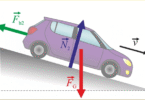
Consider a rectangular block sliding down the inclined plane of angle Q0. The block is of weight Wand is sliding freely using its weight component WsinQ. This weight component is opposed by a friction force Fr. The normal reaction is perpendicular to the inclined plane and is opposite to the weight component WcosQ of the block.
Example 2ind the static friction between a block of wood of mass 10kg and the table on which it rests. A minimum force of 50N is required to make the block just move on the table top.
Example 3
A mass is placed on an Inclined plane such that it moves at a constant speed when tapped tightly. If the angle the plane makes with the horizontal is 30º. Find the coefficient of dynamic friction.