


Join Our Groups


TOPIC 9: THERMAL CURRENT ELECTRICITY
The Concept of Electromotive Force (emf) and Potential Difference (PD)
Explain the concept of electromotive force (emf) and potential difference (pd)
Potential difference (P.d) is the difference in potential between two charged points of conductor. It is measured in volts with the unit V.
Electromotive force (e.m.f) is the voltage developed by any source of electrical energy such as a battery or dynamo. It is generally defined as the electrical potential for a source in a circui. It is measured in volt with the unit V.
Internal Resistance (r)is an opposition offered in the batteries or power supplies which have the effect of reducing the output potential difference as the current supplied increases.
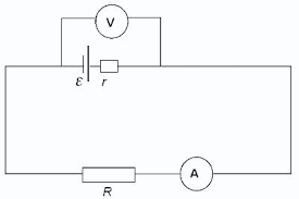
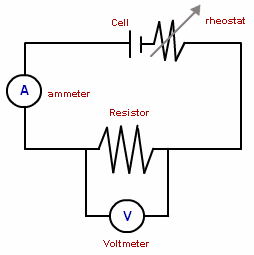
The voltmeter in the following figure shows the ‘lost volts’.
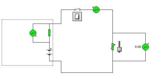
- Set the variable resistor in the circuit to 10Ω.
- Close the switch and note the values of the p.d across the internal resistance and the load resistance.
- Suppose the result shows a p.d across 10Ω load resistance of 7.5V and a p.d across the
- 2Ω internal resistance of 1.5V the e.m.f of battery is 9V.
- The p.d actually available at the battery terminals is called the terminal p.d. If the e.m.f of the battery is Vtpd = Terminal, p.d across the internal resistance = Vlost.Thus E = Vtpd – Vlost.
- The Electromotive force (e.m.f) can be regarded as the total potential difference including the potential difference lost across the internal resistance of the battery.
- The SI unit of potential difference or electromotive force is the Volt (Symbol V).
Resistance (R)is an opposition offered by resistor to the flow of an electric current.
From Ohm’s law, R = (V/I)
Resistor is a component that has resistance or is an instrument used to opposes the flow of current.
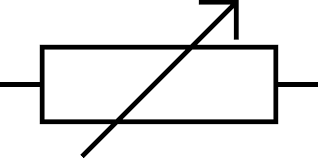
Variable resistor (rheostat) is a resistor whose resistance can be changed smoothly in order to change the current flowing.
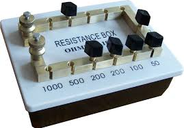
Resistance box consists of a number of resistors connect in series through thick brass blocks (any of the resistors may be short-circuited by putting a plug into the associated socket).
Wire resistorsare lengths of wire of known resistance. The resistors used in electronic circuits are made from carbon or metal film and the value of resistance is shown by colour coded rings.
Resistanceis measured inohms. The resistance of a conductor may be determined by passing a steady current (I) through it and at the same time recording the corresponding voltage across it.
The SI Units of Electromotive Force and Potential Difference
State the SI units of electromotive force and potential difference
Electromotive Force (e.m.f.) of a source is the energy converted from non-electrical to electrical form when one coulomb of positive charge passes through the source.
SI unit: Volt (V)
E=W/Q, where E = e.m.f., W = work done by source, Q = amount of positive charges
The potential difference between two points is defined as the energy converted from electrical to other forms when a current of positive charge passes between the two points.
TheSI unit: Volt (V)
V=W/Q, where V = potential difference, W = work done in driving the charge between the two points, Q = amount of positive charge.
IMPORTANT:There can be e.m.f. without a closed circuit. BUT there cannot be a potential difference without a closed circuit.
Electromotive Force of a Cell and Potential Difference
Measure electromotive force of a cell and potential difference across a conductor
Potentiometer is a device used to compare the e.m.f. (electromotive force) of two cells, to measure the internal resistance of a cell, and potential difference across a resistor. It consists of a long wire of uniform cross-sectional area and of 10 m in length. The material of wire should have a high resistivity and low temperature coefficient. The wires are stretched parallel to each other on a wooden board. The wires are joined in series by using thick copper strips. A metre scale is also attached on the wooden board.
The potentiometer works on the principle that when a constant current flows through a wire of uniform cross sectional area, potential difference between its two points is directly proportional to the length of the wire between the two points.
Electromotive force (emf) is a measurement of the energy that causes current to flow through a circuit. It is the energy provided by a cell or battery per coulomb of charge passing through it. It can also be defined as the potential difference across the terminals of a cell, when no current flows through it. Electromotive force is also known as voltage, and it is measured in volts. Electromotive force is not truly a force; rather, it is a measurement of energy per unit charge.
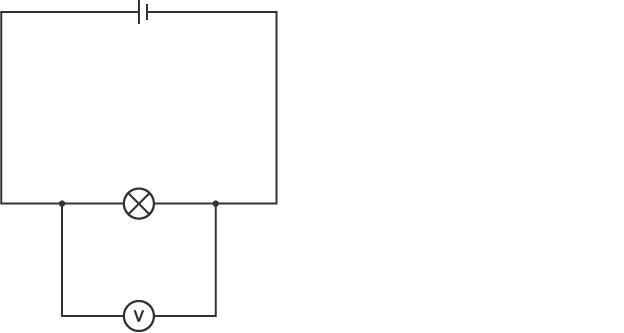
Measuring potential difference
Potential difference is measured using a device called a voltmeter. Just like ammeters, some types have a pointer on a dial, but most have a digital display. However, unlike an ammeter, you must connect the voltmeter in parallel to measure the potential difference across a component in a circuit.
A circuit diagram showing a voltmeter in parallel with a lamp
When two components are connected in parallel, you cannot follow the circuit through both components from one side to the other without lifting your finger or going back over the path you have already taken.
The Concept of Electric Current in a Conductor
Explain the concept of electric current in a conductor
Resistance of a wire: The resistance of a wire depends on the length (L) and cross sectional area of the conductor. R is directly proportional to L.
Also
R = L/A
Combine eqn (I) and (II)
R = L/A
R = K. L/A
K = Constant called Resistivity (J)
R = JL/A
J = RA/L
Resistivity (J) is the resistance of a 1metre length of a piece of a conductor whose cross – sectional area is equal to 1 meter square (m2).
Example 1
The resistance of copper wire is found to be 10Ω. Calculate the resistance of a copper wire of the same length but whose radius is twice that of the first wire.
Solution:
Let, r and J be the radius, length and resistivity of the wire whose resistance is 10Ω.
Thus
R = JL/A
But
Cross – sectional area, A = IId2/4r or IIr2
R = JL/A............................ (i)
Let 2r, L and J be the radius length and Resistivity of the wire of Resistance (R)
R = JL/II(2r)2 ....................(ii)
Divide Eqn (ii) / (i)
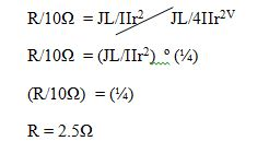
Resistance, RE of the conductor 2.5Ω
Factors which Determine the Resistance of a Conductor
Describe factors which determine the resistance of a conductor
There are three external factors that influence the resistance in a conductor. Thickness (cross sectional area of the wire), length, and temperature all have some effect on the amount of resistance created in a conductor. The fourth factor is the conductivity of the material we are using. Some metals are just more electrically conductive than others. This however, is considered an internal factor rather than an external one.
- Cross Sectional Area:The cross-sectional area of a conductor (thickness) is similar to the cross section of a hallway. If the hall is very wide, it will allow a high current through it, while a narrow hall would be difficult to get through due to it's restriction to a high rate of flow. The animation at the left demonstrates the comparison between a wire with a small cross sectional area (A) and a larger one (A). Notice that the electrons seem to be moving at the same speed in each one but there are many more electrons in the larger wire. This results in a larger current which leads us to say that the resistance is less in a wire with a larger cross sectional area.
- Length of the Conductor:The length of a conductor is similar to the length of a hallway. A shorter hallway would allow people to move through at a higher rate than a longer one.
- Temperature:The temperature of a conductor has a less obvious effect on the resistance of the conductor. It would be as hard to apply the hallway analogy as it is hard to say whether a hot hallway would make us move faster or slower than a cold hallway. To truly understand the effect you must picture what happens in a conductor as it is heated. Remember, heat on the atomic or molecular scale is a direct representation of the vibration of the atoms or molecules. Higher temperature means more vibrations. Imagine a hallway full of people. Half of the people (the electrons) are trying to move in the same direction you are and the other half (the protons) are evenly spaced but stationary in the hallway. This would represent a cold wire. Since the wire is cold the protons are not vibrating much so the electrons can run between them fairly rapidly. As the conductor (hallway) heats up, the protons start vibrating and moving slightly out of position. As their motion becomes more erratic they are more likely to get in the way and disrupt the flow of the electrons. As a result, the higher the temperature, the higher the resistance. A prime example of this is when you turn on a light bulb. The first instant, the wire (filament) is cold and has a low resistance but as the wire heats up and gives off light it increases in resistance. As a result we can say that Ohm's law holds true unless temperature changes.At extremely low temperatures, some materials have no measurable resistance. This is called superconductivity. The materials are known as superconductors. Gradually, we are creating materials that become superconductors at higher temperatures and the race is on to find or create materials that superconduct at room temperature. We are painfully far away from the finish line.
The Relationship between Potential Difference across the Conductor and Current
Determine the relationship between potential difference across the conductor and current
The relationship between voltage, V and current ,I in a metal conductor was discovered by George Ohm and formulated in a law called as Ohm’s law.
Ohm’s law state: The potential across a metal conductor is directly proportional to the current flowing through the conductor, provided that its temperature remains constant.
Or VaI , if T remains constant
Types of Resistors
Identify types of resistors
Resistors can be classified on various types based on various factors.Some of the classification of resistors are:
Based on the conductive properties of a resistor resistors can be classified as:
- Linear Resistor: A linear resistor is the type of resistor whose resistance remains constant with increase in the potential difference or voltage applied to it. Or the Resistance or Current passed through the resistor does not changes as the applied voltage ( P.D ) changes. The V-I characteristics of such resistor is a straight line as shown on the figure below or in other words these types of resistors followsOhm’s Law very strictly.
- Non Linear Resistor: Non-Linear Resistor are those types of resistors in which the Current passedthroughit is not exactly directly proportional to the Potential Difference applied to it. These types of resistors have non-liner V-Icharacteristicsand does not strictly follows ohm’s Law
Based on the resistance value of the resistor the resistors can be classified into following groups:
- Fixed Value Resistor: Fixed value resistors are those types of resistors whose value is fixed already during manufacturing and cannot be changed during its usage.
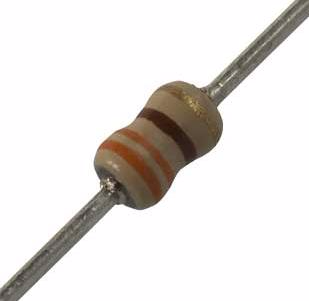
Fixed resistor
- Variable Resistor or Potentiometer: Variable Resistors or Potentiometers are those types of resistors whose value can be changed during its usage.
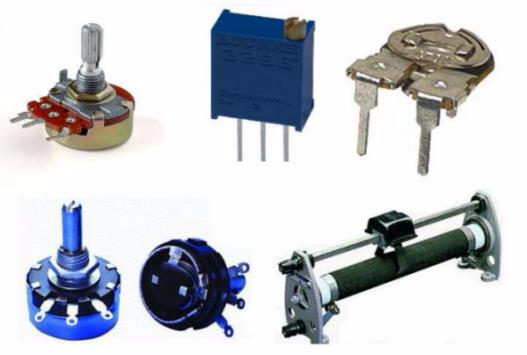
Variable Resistors
The Equivalent Resistance of more than two Resistors in Series and Parallel
Determine the equivalent resistance of more than two resistors in series and parallel
Resistor in series:To connect two or more resistors in series is to joins the resistors one to another in succession. Consider a total of N Resistors connected in series.
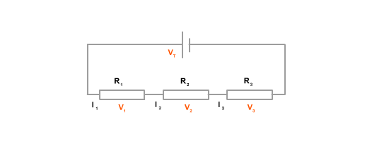
Let a current I flow through each of the Resistor R1, R2, R3 ............... RN let their total resistance be represented by only one resistor R called the Equivalent Resistance.
According to Ohm’s law, the voltage across each Resistor will be:VI = IRI V2 = IR2 V3 = 1R3 ............................Vn = IRN
The voltage V across the set of Resistor is the sum of the voltages a cross each resistor.
Thus
V = VI + V2 + V3 .................................VN
V = ( IRI + IR2 + IR3 ...........................IRN)
V = I (RI + R2 + R3 ............................... RN)
V/I = (RI + R2 + R3 ............................... RN)
But
V/I = R = (Equivalent Resistor)
R = (RI + R2 +R3 ....................................RN)
Hence equivalent resistance of resistors connected in series is resistor connected in parallel.
Now let us consider the case where a total of N RESISTORS connected in parallel to each other as illustrated.

Let;The current I, I2, I3 ... In flow in the resistor RI, R2 , R3 ....RN Respectively
I = 1, 12+13 ......................... IN
The potential different across each Resistor is the same.Suppose the P.D a cross the Resistor is V and equivalent Resistances R
Then
I = I1 +I2+I3 ..........................IN
V/R = V/RI + V/R2 +V/R3 ............................................. VN/RN
V/V (I/R) = V/V (IR1 + 1/R2 + 1/R3 ..................I/RN)
Hence the reciprocal of the equivalent Resistance in parallel is equal to the sum of the reciprocals of the individual Resistors.
Example 2
Two resistor of 3Ω and 5Ω are connected in series and then in parallel. Find the equivalent resistance when they are in series and parallel.
Solution
Equivalent resistance in series, R
R = RI + R2
R = (3Ω + 5Ω)
R = 8Ω
Equivalent Resistance in parallel, R
I/R = I/R1 + I/R2 ......................................I/RN
I/R = I/3 + I/5
(I/R) = (5+3)/15
(I/R) = (8/15)
R = (15/8)
r = 1.875Ω
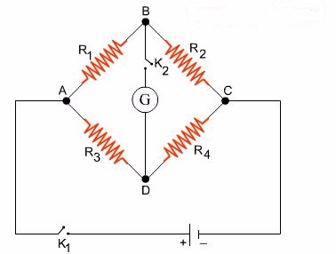
The Mode of Action of a Wheatstone Bridge
Explain the mode of action of a Wheatstone bridge.
Wheat stone bridge is an electrical circuit . In wheat-stone bridge four resistance R1, R2, R3and R4are connected end to end with each other to form a closed loop. A sensitive galvanometer "G" is connected between their junctions as shown. The circuit is provided with two keys ‘K1’ and ‘K2’. Generally wheat-stone bridge is used to determine unknown resistances.
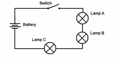
Simple Electric Circuit
Connect and analyse a simple electric circuit
A collection of devices such as resistors and sources in which terminals are connected together by connecting wires is called an electric circuit.These wires converge in nodes, and the devices are called branches of the circuit, as shown in figure below.
The general circuit problem is to find all currents and voltages in the branches of the circuit when the intensities of the sources are known. Such a problem is usually referred to ascircuit analysis.
Remarks-- While the current in a resistor has a fixed relationship with the voltage across it, the current flowing in a voltage source, or the voltage across a current source, is theoretically unrestricted and can assume whatever value governed by the external circuit.
The Mechanism of Heating by Electric Current
Explain the mechanism of heating by electric current
Electricity is the form of energy, and it can be demonstrated as follows:
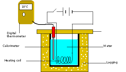
When you close key K an electric current flows thought the wire resistor and the water heats up, showing that the electrical energy is being converted to heat. Suppose the increase in temperature of the water is Q. Then, the heat gained by the water is given by:
H = MCQ
Factors which determines the Quality of Heat Generated in a Conductor due to a Current
Describe factors which determine the quality of heat generated in a conductor due to a current
H is directly proportional to Q.
- Heat absorbed by the water is proportional to the increase in its temperature.
- The arrangement used in experiment can be also used to investigate how the heat (or temperature) varies with current and resistance of the wire.
- H is directly proportional to Q.
- Heat is directly proportional to the temperature.
- H is directly proportional to I2.
- Also Heat is directly proportional to the time (t).
- H is directly proportional to t.
- Also Heat is directly proportional to the Resistance, R.
- H is directly proportional to R.
When we combine the equations, wefind that
H is proportional to I2Rt
Hence
- H = KI2Rt
- H = (IR) It
- V = IRH = VIt
- H = ItV
By Ohm’s law
- I = (V/R)
- H = (V/R) (tV)
- H = V2t/R
SI Unit of energy is Joule (J).
Equation: H = (V2t) is joule’s law of heating.
Joule is the work done when a change of one coulomb flows through a conductor with a potential difference (p.d) of 1 volt a cross it in one second.
Example 3
An electric Kettle has a wire of Resistance 5Ω. 1kg of water is to be heated from room temperature (300k) up to its boiling point (373k). Using the kettle, if we ignore the thermal capacity of the kettle, what current must flow in the resistance wire if the water is to be heated in 10 minutes?
(Specific Heat capacity of water = 4200J/Kgk )
Data Given
- Specific Heat capacity, C = 4200 J/Kgk
- Change in Temperature = (373 – 300) K=73K
- Mass of water, M = 1Kg
- Resistance of wire, R = 5Ω
- Time of the current to flow, t = 10min = 600s
Solution
The thermal energy Gained by water
H = MCQ
= (Ikg x 4200J/Kgk x 73K)
= 3.066 x 10⁵ J
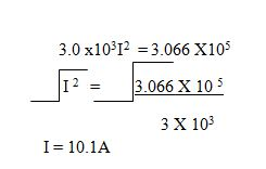
Electrical energy delivered by a current I flowing is
H = I2Rt
= 3 x 10³I2J
Thermal energy gained = Electrical energy delivered.
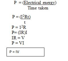
Electrical Power
Determine electrical power
Electrical power (P):Is the electrical energy delivered per Unit time taken to deliver the energy.
Every electrical appliance should Cary a label starting with the potential difference for which it is designed and the power it can convert when operating at the stated potential difference.
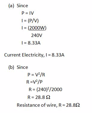
Example 4
Calculate (a) the current taken and (b) the resistance of the plate of an electric iron rated 240v, 2000W.
The Power Rating of Electrical Appliances
Interpret the power rating of electrical appliances
The commercial Unit of Electrical energy is the Kilowatt – Hour, abbreviated as KWh.I Kwh is the energy supplied in one Hour by an appliance working at the rate of 1000 watts.
IKwh = 1000 W X I hour
= (1000 x 3600)
3.6 x 10⁶J
Example 5
What is the cost of using an electric Iron rated 240V, 2000W for 10 Hours if the Electrical energy costs Tshs 100 per Unit (1 Unit = 1 Kwh).Total energy used for 10hrs = (2000W X 10hr).
= 2000Wh=20Kwh
The cost of using the appliance
1Kwh = 100Tsh
20 Kwh = X
x = (20Kwh x 100Tsh)/IKwh
x = 2000 Tsh
The cost of using appliance = 2000Tsh
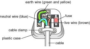
The Meaning of the Letter E (Earthing) L (Live) and N (Neutral) in Electrical Wiring
Explain the meaning of the letter E (Earthing) L (Live) and N (Neutral) in Electrical Wiring
Domestic Electricity:Is the form of electricity which is wired in the house.
LIVE WIRE (L): Is connected to one of the lower holes using a pin Brown / Red in colour.
NEUTRAL WIRE (N): Is connected to one of the lower holes using a pin is blue in colour.
EARTH (E): The upper hole is connected to the Earth wire with stripes of green and yellow lines or just green.
The Function of a Fuse and a Circuit Breaker
Describe the function of a fuse and a circuit breaker
Fuse is an electrical instrument which is composed of the thin wire of aluminum or copper insulated with rubber or plastic which melts when current exceeds its normal value. Fuse can also be described as a short piece of special wire which melts when more than a rated amount of current passes thought it.
Circuit Breakers:These are sensitive switches that turn off the current when there is a surge of current following a fault they can be reset simply by flicking the switch to the ‘on’ position.
Wiring on a Board
Perform wiring on a board
The plug; Is the device that is connected to the cable that supplies electricity to the appliance on one side and is pushed into a socket connected to the source of the mains electricity supply on the other.
Elecrical Faults in Domestic Appliances
Check and rectify electrical faults in domestic appliances
Most faults you will encounter are from a fairly simple cause. Sometimes these are easy to track down sometimes not. The key to success is to use a logical and systematic approach when trying to pinpoint the cause.
A good stating point is to get familiar with your consumer unit whether it is a fuse type or a circuit breaker type.
Identify what circuits you have and what they do:You'll probably have several lighting circuits, probably one on each floor and several socket circuits (ring circuits) one on each floor. Additionally you may have several circuits for individual applianceslike cookers, electric showers, alarms, out-door power, etc.
In the event of a fault you may find a fuse blows or a circuit breaker trips on one of these circuits. Clearly the problem is limited to that one circuit. You can try to reset the breaker or change the fuse. This may well solve the problem if it has been caused by a temporary overload.If the fuse blows again or the breaker trips you still have a fault and need to investigate that circuit.
Either, the circuit is drawing too much current(which could be the result of a faulty appliance or you've got too many appliances for the rating of that circuit),Or, there is a short circuit which means somewhere you have a live wire touching something it shouldn't, which will be due to one of several possible causes.
Appliances not working?
- Try them in another socket.
- Check the fuse in the plug (see using a continuity checker).
- If other appliances works on the socket and you've checked the fuse then the appliance is broken! Replace it or try and get it repaired by a specialist.
Simple cellis the cell consists of copper and zinc cathode with dilute sulphuric acid as Electrolyte.
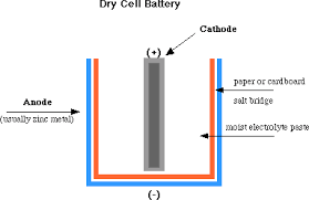
The Mode of Action of a Dry Cell (Leclanche)
Describe the mode of action of a dry cell (Leclanche)
Action of simple cells;
- At cathode: The zinc plate dissolves in the sulphuric acid solution and liberates electrons into the external circuit. The metal discus had to be of different material Volta used copper and zinc discs sand witched by cloth soaked in salt water. The combined device was called a voltaic pile. Volta also obtained the same effects by using copper and zinc plates dipped in dilute sulphunic acid. Volta called these devices, arranged in series. The “ Crown of cups” zn - 2e - Zn 2+ The 2n 2+ ions go into solution.
- At anode: Positively charged hydrogen lons (H+) are attracted towards the negatively charged copper plate2H + + 2e ----- H2.The chemical reaction in the cell creates a potential different between plates, causing electrons to flow when the two plates are joined with a wire. The electrons flow is maintained by the chemical change that occurs when the zinc dissolves in the sulphuric acid. Since simple cell, which is able to adrive an electric current through a circuit, is said to be a source of electromotive force (e.m.f)
Voltage of Combination of Cells in Series and Parallel
Determine voltage of combination of cells in series and parallel
Connecting in Series
When connecting your batteries in Series you are doubling the voltage while maintaining the same capacity rating (amp hours). This might be used in a scooter, Power Wheels kids vehicle, or other applications. Just use a jumper wire between the negative of the first battery and the positive of the second battery. Run your negative wire off of the open connector from the first battery and your positive off of the open connector on your second battery.
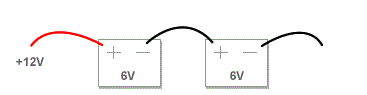
Connecting in series (double voltage, same capacity [ah]
Connecting in parallel
When connecting cells in parallel, you are doubling the capacity (amp hours) of the battery while maintaining the voltage of one of the individual batteries. This would be used in applications such as laptop batteries, some scooters, some ups backups, etc. Use a jumper wire between the positives of both batteries and another jumper wire between the negatives of both batteries. Connect your positive and negative wires to the same battery to run to your application.
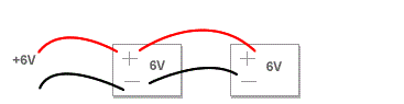
Connecting in parallel (double voltage, same capacity [ah]
The Cell Defects
Identify the cell defects
Simple Have two main defects which cause the current to diminish quickly when the cell is being used.
Two defects of simple cell are:
- Polarisation
- Local Action
Polarisation
Polarisation is the defect occurs in simple cell caused by the formation of hydrogen bubbles around the copper plate.These bubbles insulate the copper plate and prevent other positive hydrogen ions from receiving electrons from the copper plate to become neutral.
Also hydrogen ions accumulating at the copper plate repels other Hydrogen ions ( This defect is called Back e.m.f and opposes or weakens the main e.m.f of the cell).
How to minimize polarisation
- Polarisation can be minimised by using suitable oxidising agents, called depolarisers, to remove the hydrogen. An example of depolarisers for hydrogen is potassium dichromate. The dichromate oxidizes the hydrogen to form water.
Local Action
Local action is the process by which a cell is used up when no external current is flowing.Commercial zinc normally contains atoms of Iron, lead, carbon, etc called impurities.
When commercially zinc is used in a simple cell, bubbles of hydrogen are seen escaping from the zinc plate (evidence of local Action).The Impurities on the surface of the Zinc act as a second plate of a cell. As a result, Zinc dissolves in the acid even when the cell is not in use (This process wastes the zinc)
How to minimize local action
The problem of local action can be overcome by using amalgamated zinc plate (zinc coated with mercury).
Pure zinc in mercury form zinc amalgam.This is done by rubbing some mercury on the zinc plate.
The leclanche cell:Is the cell uses an aqueous solution of ammonium chloride (sal ammoniac) as the electrolyte, amalgamated zinc rod as cathode. The carbon rod as anode fixed in a porous pot, containing a powdered mixture of carbon and manganese (iv) oxide.
The carbon makes the mixture more conducting, and the manganese (IV) oxide (manganese dioxide,MnO2) acts as a depolarizer.
The Dry cell
Is a modified leclanche cell in which the main electrolyte is a paste of starch and ammonium chloride. The action of the cell is similar to that of the wet leclanche cell.
The paste is prevented from drying by sealing the top of cell with some insulating materials. This type of cell gives a larger current and have a shorter recovery (demoralising time) than the 'wet’ type;
Hence it is useful for a greater variety of applications.However, Local action cannot be eliminated completely in these cells, so that the cells have a storage (or shelf) life ranging from a few months to up to several years if stored in a cool place
The leclanche cell is called a primary cell and this type of cell current is produced from a non recoverable or irreversible chemical reaction.
Example:When all the zinc has been dissolved in the simple cell it can never be recovered to its original form by passing a current thought the cell in the opposite direction.
Secondary cell
This is the cell which can be recharged after it hasrun down (used). This is done by passing a d.c current from a dynamo or similar device through the cell in the opposite direction to that in which the cell usually supplies current in an external circuit.
Also called storage cells or accumulator some common accumulators are:
- Lead Acid accumulators
- Nickel – Cadmium accumulators
- Alkaline and chloride accumulators
The main advantage of this type of cell is that it has a very low internal resistance and can therefore give a large current with very little drop in the terminal potential difference.
The Mode of Action of Lead-acid accumulator
Describe the mode of action of lead-acid accumulator
The lead – acid accumulator cell consists of two plates of lead immersed in sulphuric acid.The acid is in a plastic container.Two or more cells may be connected to forms battery
The positive terminal is lead (iv) oxide and the negative terminal is lead.
Wood / rubber/ separator/Insulator
Cathode electrode: Lead plate (–)
Anode Electrode:lead (iv) oxide (+)
Before the accumulator is use it has to be charged
The Charging and Discharging Phenomenon of an Accumulator
Explain the charging and discharging phenomenon of an accumulator
Charging is done by connecting across its plates as source of direct current. If the current of 2A may be allowed to flow across the terminal of the cell. The positive terminals of the cell and the source of current (dynamo) must be connected together similar the negative terminal must be connected together.
If the cell is now fully charged the p.d across its terminals on open circuit is 2v, and the cell is ready for use.It can light says a2v electric lamp connected across its terminals. The currents will flow in the reverse direction to the charging current.
Discharging Accumulator
- Is the process of using charges stored in the lead – Acid Accumulator.
- When the accumulator is discharged after long use both plate become coated with lead sulphate.
- The relative density (R.D) of Acid also become less and the P.d of cell falls.
- Recharging will restore the plate of lead (iv) oxide and lead, and the relative density of acid will rise to 1.25
- The accumulator must not allowed to discharge below the stated values of p.d and Relative density, or it will not be possible to recover it on recharging.
- The capacity of an accumulator is the amount of current in amperes that the cell can send thought a circuit is measured in ampere – Hour (Ah)
- The charging rate an Accumulator is a current in amperes, numerically equal to one – tenth (1/10) of the capacity required in Recharging.
- Lead-acid accumulators have high e.m.f (2v per cell) and allow internal Resistance.
- Accumulators are best cared for by a regular check of the level of the sulphuric acid.
- Any loss due to evaporation must be replenished with distilled water only.
- No acid should be added unless there has been same spillage from the cell.
- Accumulators must be recharged regularly using the charging current recommended by the manufactures.
- They should not left in discharged condition for a long time.
- When not in use they should be recharged at least once every month.
- An accumulator should never be short-circuited.
- Shorting the cell may cause swelling and buckling of the plates due to excessive heat developed in the cell, leading to permanent damage (A cell in this condition is said to be sulphated).
Cells and Accumulators in Daily Life
Use cells and accumulators in daily life
Uses of electric cells
- Electric cells are very useful when no mains supply of electricity is available or when connecting to a main supply of electricity would be inconvenient.
- Portable radios, torches, calculators and watches are example of devices that use primary cells.
- It is possible to buy rechargeable batteries for these devices.These are secondary cells to start the engine and to run all the electrical circuits.
- This cell is recharged by the alternator when the car is in use.


Nice
ReplyDelete