Join Our Groups
TOPOGRAPHICAL MAP INTERPRETATION
We have Three Types of Notes for you
Notes 1, Notes 2 and Notes 3
NOTES 1
Definitions of Map
- Map is a diagrammatic representation of an area of land or sea showing physical features, cities, roads, etc.
- Map is a drawing of the earth's surface, or part of that surface, showing the shape and position of different countries, political borders, natural features such as rivers and mountains, and artificial features such as roads and buildings.
- Map is a representation usually on a flat surface of the whole or a part of an area
- Map is a drawing of a particular area, for example a city or country, which shows its main features, such as its roads, rivers, mountains etc
- Map is a symbolic depiction emphasizing relationships between elements of some space, such as objects, regions, or themes.
 |
| Map of Tanzania |
Map reading is the process of identifying features on a map by using symbols and signs or names. This technical work requires certain skills that any map reader must possess.
Map interpretation is the interpretation of the symbols and signs used on map into ordinary language by indicating the features they represent and draw logical conclusions from the information as represented by the symbols.
Cartography is the study of making or drawing maps
Cartographer is a person who draws or produces maps
TYPES OF MAPS
According to Functions:
1. Topographical Maps. Are maps which show physical features which are natural features e.g. mountains, valleys, hills etc and man-made features e.g. bridges, ponds, roads, settlements etc
2. Statistical Maps. Are maps which show the distribution of things in quantitative manner e.g. distribution of rainfall, temperature, crops etc.. Examples of statistical maps are dot maps, choroploth maps, Isoline maps etc
According to Scale Size:
1. Large scale maps. Are those maps drawn to large scale size e.g. 1:10000 These maps gives a larger representation of small area, they are also more detailed (shows a lot of information). They represent areas like cities, towns and villages.
2. Medium Scale Maps. Are those maps drawn to medium scale size e.g. 1:100000 They show a moderate amount of details. They represent areas like districts, regions and countries.
3. Small scale maps Are those maps drawn to small scale size e.g. 1:1000000 They give a small presentation of a large area; they show little content (little information) They represent areas like continents and the world.
 |
| Topographical Map |
Importance of Map Reading
1. They provide basis for description of geographical phenomenon
2. They are useful for traveling purpose i.e. they guide people to reach their destination
3. Maps are useful for storage of geographical information
4.They are important for field studies
5. They are important for land use planning
6. They are useful for military purposes e.g. during wars.
ESSENTIAL ELEMENTS OF A MAP
The basic skills required in understanding how to read a map include Title, Scale, Key, Indication of the north direction, Margin/Boundary and Date of compilation.
1. Tittle gives the name of the country and the area where mapped. It helps the map reader to know what the map is all about. The heading is usually printed in bold capital used on the map
2.Scale is a ratio between the distance on the map and actual distance on the ground. It is used to find actual distance and areas on the ground. On topographical maps scales are given in form of ratio or lines
3. Key / legend is a feature which explains the signs and symbols which are used on the map. Not all symbols which are used in the key are applicable to the particular map but all signs and symbols applied on the map are shown on the key. Definition of terms which should be added on others terms under the tittle "Basic skills of map reading/Essential elements of a map" are " margins/Bounder
4. Indication of north direction. It gives an idea about the orientation of the map especially in identifying where the north direction is.
5.Margin/Boundary. A frame which borders the map. This guide and limit the map user in reading and interpreting the map. The aim of the margin is to enclose the area covered by the map
6. Date of compilation. Gives the publisher name and when the map was published. This date is important because physical and human settlements features changes with time but the map drawn representing the land does not. For instance between 1960 and 2007 Dar es salaam has changed in many ways.
Measurement of Distances on Maps
Distance is the length of elongated features on the earth’s surface such as road, railway, river etc. How to measure distance. In order to obtain distance of any feature on the map, consideration should be made on whether the distance to be measured is straight or curved. Straight distance For all straight distances a ruler is used to obtain the distance directly from the topographical map given. Curved distance. It becomes difficult to obtain curved distance of the features by the use of a ruler directly from the topographical map when the area is inclined.
Distances on maps can either be straight or curved (bent). A straight or regular distance is one that has no bends or curves while a curved (or irregular) distance is the one with bends or curves.
Distances on maps can either be straight or curved (bent). A straight or regular distance is one that has no bends or curves while a curved (or irregular) distance is the one with bends or curves.
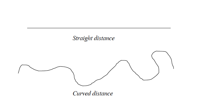
Tools for measuring distances
There are three main tools that are used for measuring distances on maps. These are:
- a long, thin string or thread;
- a piece of paper; and
- a pair of dividers.
Measurement of distance using a thread or string
A long, thin string such as sewing thread can be used to measure a stretch of many curves or bends. This is the commonest method used by geography students to estimate distances on maps. This method is also used to estimate straight distances.
Procedures
- Identify the distance to be measured on the map (e.g. a river, road, railway line, etc) and mark its two ends with a sharp pencil. Mark one end as A and the other as B.
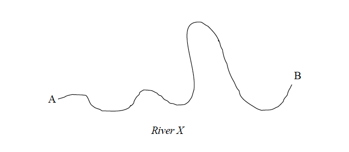
- Starting from one end of the string, trace the route (river, road, etc) with a string as shown in the figure below:
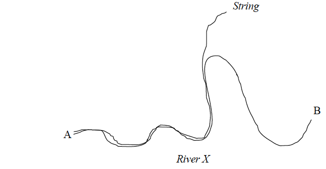
- Mark the string with an ink at point B.
- Using a ruler or linear scale, measure the length of the string between point A and B and estimate the actual distance on the ground using the scale of the map provided.
Example 2
If the length of the section of the string between A and B is 20 cm and the scale of the map is one centimetre to one kilometre, then the length of the route on the ground is 20 km.
Measurement of distances using a piece of paper
A piece of paper can also be used to measure straight and irregular (curved, bent) distances
Measuring straight distances
Procedures
- Locate the distance to be measured on the map and mark its two ends as A and B using a sharp pencil.
- Take a piece of paper, fold it to form a straight edge and lay the edge along the line AB and mark the exact length of the line on the edge of the paper as shown in the figure below.
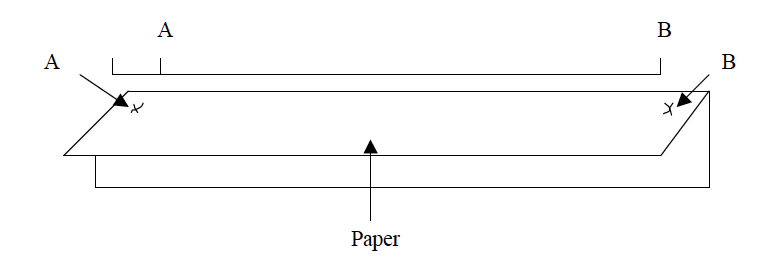
- Transfer the paper to a linear scale (or ruler) as indicated in the figure below so that the left hand mark (A) is on 0 (zero).
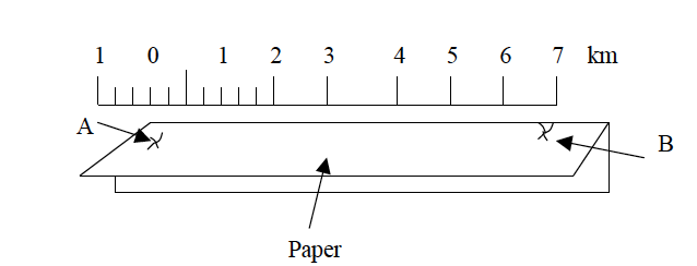
- Use the provided scale to estimate the actual ground distance.
Measuring irregular (curved) distances
Procedures
- Identify the length to be measured on the map. Use a sharp pencil to mark both ends A and B.
- Divide the route into sections which are more or less straight as shown in the figure below.

- Lay the straight edge of the paper on the first straight section of the route. Mark with your pencil where the route bends (point 1).

- Turn the paper so that the edge now lies along the second part of the route. Make sure that the mark you made is still on the point where the route bends. Now make another mark with your pencil at the bend (point 2).

- Continue shifting the paper and marking the other distances between the points on the route.
- Remove the marked paper, and using a ruler, measure from where you started to the last mark on the paper. If this distance is 20 cm and the scale is 1 cm to 1 km, then the distance of the route between A and B is 20 km.
Measuring distances using a pair of dividers
Measuring straight distances procedures
- Locate the distance to be measured on the map and mark its two ends using a pencil.
- Use a pair of dividers to measure the distance between the two end points on the map.
- If the distance is longer than the length of the dividers even when fully stretched measure the distance in sections and then sum up the lengths of all sections to get the total length.
- Place the divider on the linear scale and read the distance. Then use the scale to convert the obtained map distance into the actual ground distance.
Measuring irregular (curved or bent) distances
- Division method
- Stepping method
Division method
Procedures
- Divide the river, road, railway, etc into many, short straight distances.
- Open your dividers and measure all distances as shown in the figure below.
- Add up the map lengths of all sections along the route.
- Use the linear scale to get the actual ground length from the sum obtained in (iii) above. The length of the route is equal to the sum of all sections, divisions or short distances.
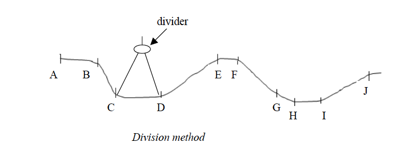
Add up all the measurements: AB = 1 km; BC = 1 km; CD = 1 km; DE = 2 km; EF = 0.5 km; FG = 2 km; GH = 0.5 km; HI= 1 km; IJ = 2 km = Total length = 10 km.
Stepping method
- Open and set the pair of dividers to a known distance by using the linear scale e.g. quarter or half a kilometre as shown in the figure below.

- Follow the river, road or line by stepping along it using the set dividers.
- Add up the number of steps and multiply by quarter or half a kilometre (depending on the set length).
Example 3
Suppose number of steps when the divider is opened to a quarter kilometres wide is 20 and when it is a half, kilometre is 10. Then, the length of the route is:
10 x ? = 5 or 20 x ? = 5 kilometres
Note that if the distance of the last step is less than the set distance of the dividers, measure it separately and estimate its distance on the linear scale. Add up this distance to the total distance from the steps to get the full distance of the route (river, road or line).
Areas of Regular and Irregular Figures
The figures whose areas are to be calculated on maps can either be regular or irregular
Calculating areas of irregular shapes
Features with regular shapes on maps are rectangular, triangular, square or circular. Finding the areas of such figures is simple. Mathematical formulae are used to calculate their areas. However, it is not common to find regular features on maps.
Calculating areas of different regular shapes
- Triangles = L x W, where L = length and W = width.
- Squares =L2, where L = length of the side of a square.
- Triangles = ?bh, where b = length of the base and h = length of the height.
- Circle = πr2 or πD2/4, where r = radius, D = diameter and π = 3.14 or 22/7
Calculating areas of irregular shapes: Features with irregular shapes are very common on maps. These may include shapes of lakes, forests, plantations, settlements, marshy land, etc.
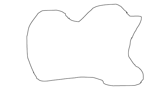
An irregular shape
There are three methods used to calculate areas of irregular shapes. These are the:
- division method;
- tracing method; and
- grid square method.
Division method
In this method, the area to be measured is divided into rectangles or squares and triangles or into several strips of the same length and width. Then, the area of each resulting figure is calculated using mathematical formula and summed up to get the total area.
- Divide the whole area into rectangles, squares or triangles.
- Calculate the areas of the rectangles, squares and triangles using mathematical formulae.
- Sum up individual areas to get the total area Remember that the area should be in the same units as the map scale.
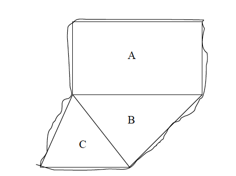
Example 4
The area above is divided into three figures A, B and C. The area of the three resulting figures is calculated as follows:
Rectangle A: Area = L x W = 10 x 5 = 50 km2
Triangle B: Area = ½bh = ½x 6 x 4 = 12 km2
Triangle C: Area = ½bh = ½x 4 x 3 = 6 km2
Total area = A + B+ C = 50 +12+6 = 68 km2
Division of the area into strips
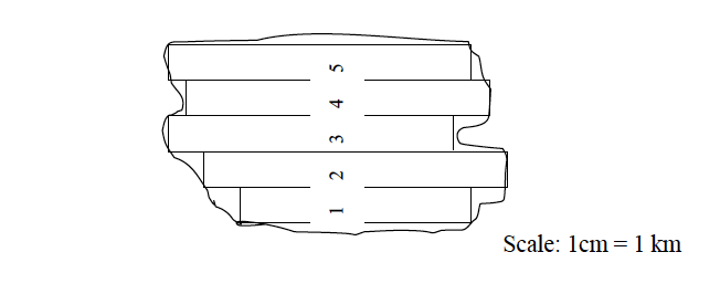
The stripping method involves dividing the area into strips and then calculating the area of each strip separately. The total area is obtained by summing up the areas of all rectangular strips.
Procedures
- Divide the area into uniform rectangular strips.
- Calculate the area of each rectangular strip separately. Remember that the areas of the strips should be in the same units as the scale of the map.
- Add up the area of each strip to get the total area.
Area = sum of the areas of all individual strips = area of 1 + 2 + 3 + 4 + 5
Tracing method
- Trace off the outline (boundary) of the figure to be measured onto a tracing paper (graph paper) or ordinary tracing paper and transfer the outline onto a squared paper.
- Tick and count all complete squares and sum up their areas. Remember that each full square measures 1 cm x 1 cm.
- Mark all incomplete squares with crosses.
- Count all incomplete squares and divide the sum by 2 to get the number of complete squares.
- Add up the squares in (iii) and (iv) to get the total number of squares covering the area of the figure to be estimated.
- Using the scale provided, find the area of one square in order to obtain the actual area that would be covered on the ground. Note that the area that you calculate is the approximate area.
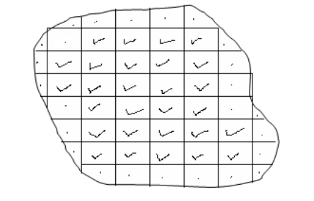
According to the figure above, the number of complete squares is 28. The number of incomplete squares is 25. To get the complete squares, we divide 25 by 2, i.e., 25 ÷ 2 =12.5
Hence the total number of complete squares = 28 +12.5 = 40.5. This is the same as 40.5 cm2.
Assume that the scale of the map is 1:50,000. Then, the area of 1cm by 1cm on the ground is 0.5 x 0.5 km = 0.25 km2
Therefore, the total actual ground area of the irregular shape is calculated thus: Area = 40.5 x 0.25 =10.125 km2.
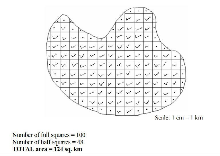
Remember that if you don’t have the tracing paper you can draw the squares straight on the map using the following procedures:
- Mark by a pencil the margin of area to be measured.
- Using the grid reference lines as your guidelines, draw the squares with faint pencil lines across the area. If there are no grid lines make sure you draw right angled squares across the figure.
- Mark your full squares and half squares and follow the above tracing method procedures for calculating the area.
The grid square method
If the map provided has grid lines, the grid square method can be used to calculate the area on the map. The grid squares formed by the lines are used in this case. For example, in a topographical map of scale 1:50,000 the distance between two successive grid lines is 2 cm. This length is equivalent to 1 km on the ground. Therefore, every grid square on a 1:50,000 map represents 1 km2 on the ground. Consider the diagram below:
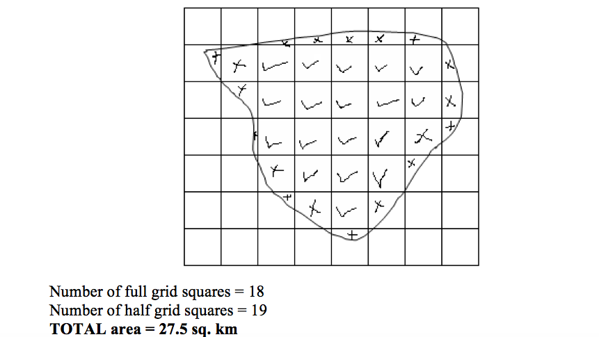
The procedures for calculating the area of a figure on a map with grid squares are similar to those used in the tracing method discussed previously in this chapter.
Location of Position
In map reading, position is a place where an object is situated on the earth’s surface. The geographic position of a place may be shown by using:
- Place names
- Compass bearing
- Latitude and longitude
- Grid reference
- Political and administrative boundaries
Use of place names
Names of places on maps may be used to locate the position of an area or place. Names of places e.g. Morogoro, Tarime, Mbeya, etc are clearly marked and shown on maps.
Compass bearing
Many years ago it was discovered that a magnetized piece of iron or needle, if hung or allowed to swing freely, will always point to the same direction. This direction is called the North. It is from the north direction that we measure other directions, that is, East, West and South.
A compass is an instrument used to measure directions from the north. It consists of a free-swinging, magnetized needle which points to the north and south magnetic poles.
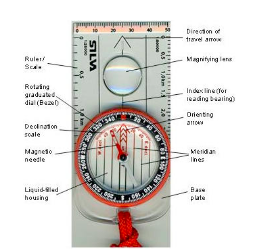
A compass
The compass can be used to show directions in the following ways:
North direction
The north direction may be shown by using; Geographic or True North; Magnetic North and Grid Nortn.
- Geographic or True North is the direction towards the North Pole from any place on the earth’s surface. It is always indicated by the north arrow. When reading directions on maps we usually use the True North.
- Magnetic North is the direction to which the compass needle points. The magnetic North is some distance from the True North and also varies from year to year in relation to the True North.
- The Grid North is the direction towards the north in those maps drawn to grid system.
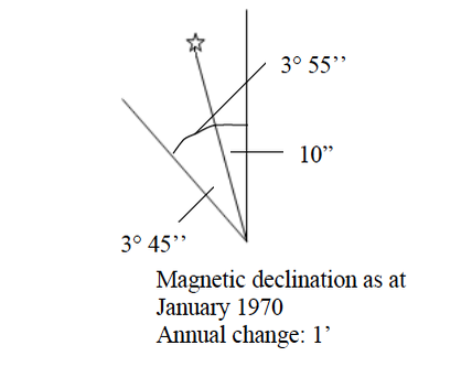
Compass directions
There are four major directions, bearings or cardinal points on maps with respect to a fixed point, be it true North or magnetic North. They are marked by 90º.
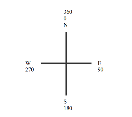
The four cardinal points can further be sub-divided into eight points of 45º
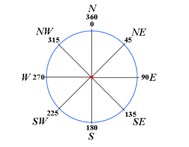
The eight points of a compass can further be sub-divided into sixteen points of 22.5º
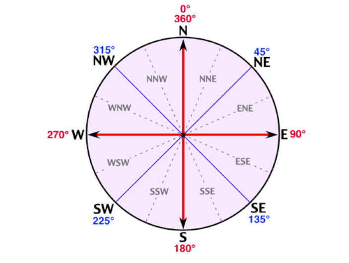
Bearings of a compass
Compass bearing shows the direction of a point with respect to another point measured clockwise from 0o to 360o. Bearing is expressed in degrees which are further sub-divided into minutes and seconds.
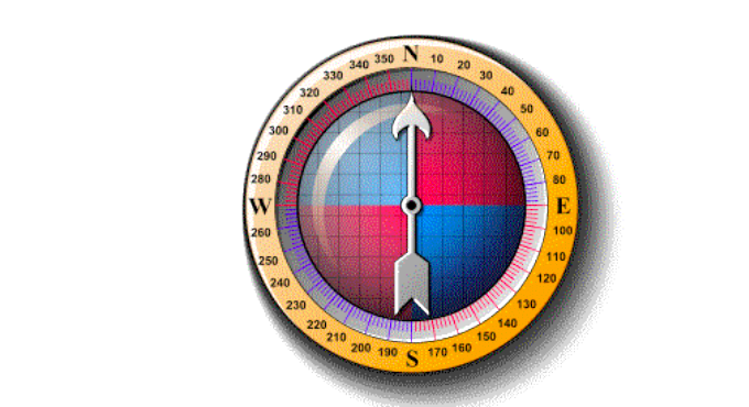
Bearings of a compass
Grid reference
A grid system is a pattern of horizontal and vertical lines forming squares of uniform sizes drawn on a map. Grid system is numbered East and North and is referred in terms of Easting and Northing.
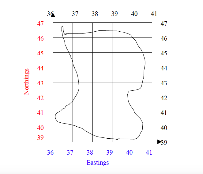
Grid lines are not lines of latitude and longitude, but are drawn to a definite distance apart, which varies according to the scale of the map and unit of measurement used in a map. The reading in a grid system is referred to as grid reference and is given in a six-figure number.
Using grid reference
- The full grid reference is given in a six-figure number.
- Easting – the eastward direction or reading are always given first.
- Northing – the northward direction or reading follows after the Easting.Example Easting = 351 Northing = 421 Full grid reference = 351421
- When a place or point falls on the main gridlines or bisected by the grid line, add 0 to each reading Example A place is bisected by:- Easting =35 Northing = 40 The grid reference of a point will be 350400
- When a place or point falls in the middle of a grid square, the grid square is sub-divided into ten equal squares or tenths. The grid reading or direction is given to the nearest tenths. Consider the point, A, in the figure below). Example See point B in the figure below. The point lies between the following grid reference: Easting = 35 Northing = 42
Procedures
- Divide the grid square into tenth to locate the point or place. For example, point A in the figure below lies at:- Easting = 5 tenths Northing = 5 tenths
- Read the easting adding the 5 tenth digit = 565
- Read the nothing adding the 5 tenth digit =225
- Full grid reference of the point is 565225
Direction and Bearing of Object on Maps
The bearing of a lace on a map can be found when the north is given. The North is usually an arrow sign pointing to the north.
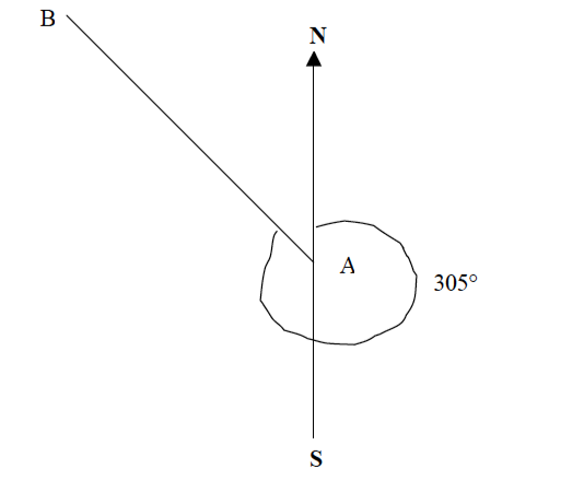
Example 5
Find the bearing of point B from point A.
Procedures
- Join points B and A with a straight line.
- At point A, draw a line parallel to the north-south line.
- Using a protractor, measure the angle B from the north towards line BA as shown below.
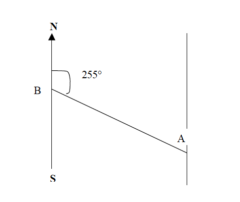
Direction of a place
The direction of a place or point is its direction with respect to another point measured by using the points of the compass e.g. North, South, East and West.
Example 6
Find the direction of point B from point A.
Procedures
- Join points A and B with a straight line.
- At point A, draw a line parallel to the north-south line or compass direction sign that is given on a map.
- Draw a horizontal line at point A to get the East and West of the four points of the compass.
- Find the direction of point B from A to the nearest point of the compass. The four, eight or sixteen points of a compass may be used.
When finding angular bearing or direction of a compass, always use the “True North” which is given on the map.
READING AND INTERPRETING TOPOGRAPHICAL MAPS
Topographical maps are types of maps which describe the physical (natural) and man-made (artificial or cultural) features of a given area. The physical features include relief, vegetation, and drainage, among others. Some of the cultural or artificial features are roads, railways, cities, towns, dams, schools, and many other structures built by man.
1. DRAINAGE
Drainage is the plan or layout of the river with its tributaries until it reaches its destination i.e. lake, main river, swamps or an ocean, therefore the concept drainage includes rivers , swamps, lakes, waterfalls ,flood areas
Note: The common drainage shown on the map is rivers, swamps, lakes and ocean. But expect to see even waterfalls especially on coloured topographical map.
DRAINAGE PATTERNS
This is the plan or layout of the river with its tributaries, or the network displayed by a river and its tributaries. Drainage of the river usually posses different network/system depending on the way how tributaries convey to the main river and the general appearance, hence drainage pattern
Types of Drainage Patterns
The following Patterns are Commonly Displayed in Topographical Maps:
1. Dendritic Pattern
Is a pattern in which its tributaries convey (join) to the main river at an acute angle resembling to the shape of tree trunk and its branches. Dendritic pattern are common in areas of gentle slope and of uniform (homogeneous) rock hardness. Therefore it can be made from granitic or metamorphic rock
2. Trellised Pattern
Is the pattern in which its tributaries convey or join to the main river at almost right angle. This type is commonly found in areas with severe cracks or fractures mostly to the rocks with an alternate hard and soft rock. Therefore this is associated with sedimentary rocks.
 |
| Trellised Pattern |
3. Radial Pattern
Is the pattern or layout in which its tributaries flow outward from the center (summit) or at the peaks of mountains. Its pattern resemble a spoken ring of bicycles where stream flow out in every direction from the center. Therefore radial drainage pattern is commonly associated with volcanic mountains /region composed of granitic rock or igneous rock
4. Centripetal Pattern
Is the pattern in which almost all streams are following from all direction converging to the center can be to the swamp, lake or depression. The determinant factor of stream flow is a slope .Therefore the drainage pattern can be associated with sedimentary rock.
5. Rectangular Pattern
Is a pattern which resemble trellised, but it has tributaries joining the main river at a right angle. The pattern is common in areas which are faulted. Therefore can be found along sedimentary rocks/granitic rock or any faulted rock.
 |
| Rectangular Pattern |
6. Annular Pattern
Is the pattern with series of streams flowing on flanks or around the dissected dome, depression or crater. Where there are an alternate band of soft and hard rocks. Note: This type is not so common, but is found around Lake Bosumtwi in Ghana .Is commonly found in areas affected by back tilting.
7. Parallel Drainage Pattern
This consists of a series of streams running parallel to one another. In some cases, streams may flow into one big river. It is common in areas of uniformly dipping rocks such as fault scarps or recently emerged coasts. Rivers Athi, Nairobi, Ruiru, Chania, Thika and Sagana in Kenya.
 |
| Parallel Drainage Pattern |
2. ROCK TYPE / STRUCTURE
The surface rock on the topographical maps is not directly indicated. They some clues are needed in order to identify rock type and structure of the mapped area.
The Indicators Used to Show the Type of Rock presented in a certain Area:
1. LAND FORMS
Land forms shown on the topographical maps help on interpretation of rock type for example:
a) The presence of volcanic land form such; crater, caldera, name of the volcanic mountains suggest the presence of igneous rock.
b) The presence of erosion and depositional features such as depression, sand dunes, coral reef suggest the presence of sedimentary rock. Flood plain suggests sedimentary rock.
c) The presence of highland with steep slope indicated that rock are hard and resistance rock that may indicate presence of metamorphic rock.
2. VEGETATION
a) Thick forest suggests the presence of igneous rock.
b) Poor vegetation cover suggests the presence of sedimentary rocks or metamorphic rock.
c) Nature of the rock. Absence of streams indicates that the rocks are permeable. Thus this depict that the rock is soft which can either be sedimentary, limestone or sandstone.
d) Presence of many streams on surface, indicate that the rock are impermeable such as igneous or granitic rock.
3. RELIEF
Read the contour and the conventional symbols or signs on the map to identify types of relief. Can either be highland relief with lower arts or lowland relief. Describe the relief with associated land forms. When you determine types of relief first look on the units on vertical interval (V.I) whether the unit is in meters or feet. If units are in feet take the highest value the convent into meter finally determine type of relief (1m=3.3ft)
 |
| Relief |
4. CLIMATE
Climate is the average weather condition experience in a given area over a long period of time not less than 30 years. Topographical maps may be used to identify the climate of given mapped area. Some hints used in interpreting climate from topographic map Latitude of the area.
a) Distance from equator used to determine kind of climate of a certain area. For example the area with latitude 5 degrees north or south of equator the area is considered to be in equatorial climatic condition while the area between 5 to 15 N/S is in tropical climatic condition, 15-30 N/S of the equator imply Semidesert 30-40 N/S implies desert climate or Mediterranean climate.
b) Water bodies. a general high density of streams indicates that the area receives high rainfall, presence of low density or seasonal streams, salt lakes and boreholes indicate aridity.
c) Vegetation, presence of forest in the map indicates heavy rainfall while woodland vegetation indicates moderate rainfall. shrubs, thickets and grassland indicate dry condition or light rainfall Crops, crops grow in those areas where water and temperature conditions are favorable for their growth. For example area with tea, coffee and sugar cane indicate that area receives heavy rainfall.
Crops such as cotton, sisal and sorghum indicate medium rainfall Relief/altitude, altitude of features such as high mountain or mountain ranges and plateaus tend to have orographic rainfall and forest making them makes their own mountainous climate. Mountains do also create their own climate due to effect of aspect which creates rain shadow.
5. HUMAN ACTIVITIES
Topographical map may contain information on economic activities undertaking usually the following are shown on topo maps.
1. Agriculture: look on the presence of Rural settlement in absence of other activities scattered cultivation storage houses/center plantation or estate (indicate large scale agriculture) industry such as Ginneres, Hulleries and Decotecator. seldom symbols or signs are used e.g. S-sisal, CC-coffee, Su-sugarcane
2. Pastoralism: look on the presence of cattle market-cattle dips veterinary installation (Vet. Office)/center Creamers (lace where milk, cream butter and cheese are processed Scattered vegetation or dominated by scrub/shrubs) Bore holes (Bore holes (BH) or water hole (wh)
3. Mining: look on the presence of; symbols of PIC () and shovel (salt work quarrying Roasting Sign Tin-TN, Iron-Fe.
 |
| Mining |
4. Fishing: look on the presence of; water bodies such as lakes, seasonal swamps, rivers, dams, ocean. These should be surrounded by settlement.
 |
| Fishing |
5. Trade and Transportation; look on the presence of Road, railway, towns and market
 |
| Trade and Transportation |
6. Lumbering; look on the presence of; forest with track-roads ending on their edges. Saw-mill Sao hill forest -Note: thicket, scrubs/shrubs and bamboo trees cannot be exploited as a timber.
7. Tourism: look on the presence of; National parks, Game reserve Recreational centre’s e.g. museum, archives beaches etc Landscape e.g. crater depression etc.
 |
| Tourism |
8. Administration: Various administrative activities can be identified from abbreviations on the map. These are given in a list in the margin of the map. They include:
a) Provision of security as evidenced by the presence of a Police Station or Police Post
b) Judicial services as evidenced by the presence of courthouse
c) Other administrative offices such as District Commissioner (DC)
d) Regional Commissioner (RC).
6: SETTLEMENT
A settlement is a place where people live. It may be as small as single house in a remote area or as large as a mega city.
Types of Settlement
There are two types of settlements which include, urban settlement and rural settlement.
a) Urban Settlement; Is commonly found in areas of District administrative centers, Regional administrative centers, and Capital city of a country.
b) Rural Settlement; Is an area where the majority of people approximately to cover 80% engage in agriculture
SETTLEMENT PATTERNS
It is a layout of dwellings in a particular place. The signs showing settlements on topographical maps are observed to have varied arrangement. The most common pattern include the following:
1. Dispersed Settlement Pattern: It is alternatively called scattered settlement pattern. The houses are widely spaced one to another
3. Linear Settlement Pattern: Houses are concentrated along an elongated objected of economic significance like a road, river, railway lines and others
Factors Encouraging Settlements
1. A reliable source of water supply e.g. presence of permanent rivers, lakes.
2. Gentle slope i.e. people prefer to establish settlement in less hazardous areas
3. Good soil for agriculture
4. Pleasant climate condition
5. Transport and communication.
WAYS OF SHOWING POSITION ON A MAP
A place can be located by its name where it is found. A more accurate way of locating a place is the use of latitudes and longitudes, this method is used by scalars at sea and aircraft in their flights. Generally position of any place can be located by using;
- Place names
- Bearing
- Latitudes and longitudes
- Grid reference
Methods of Showing Relief on Topographical Map
1. Contour Lines
These are lines drawn on topographical maps to join all places or areas with the equal height or attitude from the mean sea level. Contour are very important in determining relief features whether the relief is steep sided or gentle sloping.
This is a point on a map with its exact height fixed usually on a hill top, mountain peak or other visible positions. They are the highest points on any locality. The trigonometrical points are commonly marked by a triangle followed by the numbers indicating the height for example Δ725
3. Spot Height
Spot height is a point on a map with its exact height above a known level e.g. from the
sea level. The position and height of the points have been determined by surveyors. The spot height is marked with a dot followed by the numbers indicating height of the land for example .750
Is also done to show the relief features on the map, different coloring shades on the map to indicate different heights
5. Hachures
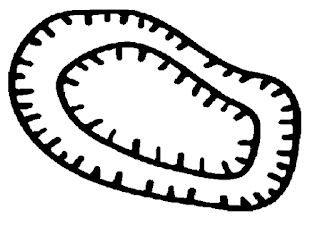
Huchures are short, broken lines drawn on a relief map showing direction and steepness of a slope
6
Form lines are usually unnumbered lines drawn on a map joining of nearly the same height areas, Are broken lines drawn between two contour lines
Relief Features on Topographical Maps
1. Ridge. Ridge is a narrow and long relief feature with steep slopes on all sides.
2. Escarpment
An escarpment is an area of highland with very steep slopes on one side and a gentle slope on another side. The steep slope of an escarpment is called the scarp slope and the gentle slope is known as dip slope.
A plateau is an extensive highland region and whose top surface is almost flat. A plateau is easily identified on the map by the absence of contour lines on the higher land surface and with a series of contours close together on either sides.
4. Slopes
A slope the inclination or slant of the land. This inclination varies considerably, resulting in the following types of slopes A concave slope are widely spaced at the lower ground and closely spaced at the higher ground. A convex slope on the other hand has a steep slope at the lower ground and a gentle slope at the higher ground. Contours of this slope are closely spaced at the lower ground and widely spaced at the higher ground. However some slopes bear both characteristics, a concave slope is gentle at the lower ground and gets steeper at the higher ground.
5. Col. A Col is the land between two peaks of a mountain or in the mountain ranges.
 |
| Col |
6. Saddle (pass). A saddle is generally wider than a col. Saddles provide convenient passages across mountain ranges. Contours showing peaks are usually closed.
6. Valley. Valley is the low lying part of the land which is bound over higher ground and steep slope. Valleys are indicated by contours forming ‘V’ shape pointing the higher ground and some valleys have rivers flowing in them.
 |
| Valley |
7. Spur. Spur (Salient) is a projection of the raised land from the side of a hill or mountain into lowland, contours showing a spur form a ‘V’ shape pointing to the lower ground.
8. Hills/peaks. A hill is a rounded upland area not as high as a mountain. Hills rises above the general relative low ground but less than a mountain. Hill height is usually about 350m-650m. Some hills are regular while others are irregular.
9. Cliff
A cliff is described as a steep rock face that is vertical or nearly vertical. Cliffs are common in mountainous or hilly areas and along the shores of lakes and seas. On topographical maps, cliffs are shown by contours that are so closely packed that they appear to merge into one another. To emphasize the presence of the cliff, a special symbol is drawn on top of the contours as shown in the figure below.
A plain is a continuous tract of relatively flat land covering a broad area of lowland. Some plains may be raised but the slopes are very gentle. Plains occur as lowlands and at the bottoms of valleys but also on plateaus or uplands at high elevations. On topographical maps, a plain is shown by contours that are very widely spaced. Some rivers, if present, may be seen to have meanders.
11. Depression.
A depression on a contour map is shown by contour lines with small marks pointing towards the lowest point of the depression. The first contour line with the depression marks and the contour line outside it have the same elevation.
12. Mountain. This refers to the upland or highland over 1000m from the mean sea level
 |
| Mountain |
CROSS SECTION
This used to show variation of relief across a region. The following stages are followed in drawing cross section:
1. Two end points of the area in question are marked AB
2. Join the two points with straight line by a pencil
3. Take a piece of paper measure from point A to B
4. A vertical scale is now required after marking the values of contours on the paper.The horizontal scale of the cross section is in the same scale as that of the map from which the line AB is taken. The highest contour line on the map is 100m
5. The horizontal base line represents sea-level; the marked paper is placed along the base line so that A on the paper falls on A on the scale. Then each contour along the horizontal line is marked with a pencil and ruler, vertical lines are lightly drawn up to the line which represents the contour height.
VERTICAL EXAGGERATION
Vertical Exaggeration (V.E) is a number of times by which the vertical scale is larger than the horizontal scale. In Mathematics V.E expressed, V.E=(Horizontal scale (HS) /(Vertical scale (VS)) Horizontal scale is the map scale/ground scale Both HS and VS should be the same units of measurements when calculating VE For example
if a map scale were 1cm to 100000cm and the vertical 1cm to 100m, the
VE is first converted from 100m to cm VE = 100000cm/10000cm VE=10cm
INTER VISIBILITY
In reading the map it is important to know from a map whether one place is visible from another or not. In cross section two places A and B were to represent two observation points weather the two places are inter visible or not. To explain inter visibility we look in the cross section if between the points (A to B) a mountain or hill develops we say the two points are not inter visible because the hill is an obstacle When the basin of depression develops we say the inter visibility, as a line of sight when drawn straight i.e. not obstructed But inter visibility can be affected by other factors such as buildings, vegetation etc.
GRADIENT
Gradient is the term refers to the measure of slope. Gradient/ slope are measured by comparing vertical distance to the horizontal distance. In map reading the calculation of gradient is done by comparing the vertical interval between two places and the horizontal distance between them.
Vertical Interval (V.I) is the difference in height between the two places; it can be obtained by subtracting the altitude of the lower point from the altitude of the higher point. V.I = highest contour
Lowest Contour The horizontal distance is measured on the map then it is converted into ground distance by the use of the map scale In calculating gradient both vertical and horizontal lengths must be brought to the same unit of length The formula for gradient Gradient =(Vertical interval ) / ( Horizontal distance)
Calculating Gradient
Example: Given; highest contour 700, lowest contour 300
V.I = 400m Length from point A to B is 8.4 cm Scale of map 1cm to 2km Calculate the gradient
Solution
Step 1: Change 8.4cm into ground /map scale 1cm to 2km 8.4cm to x =16.8km
Step 2: Change the ground scale into meters 1km =1000m 16.8km =? =16800m
Step 3: Gradient=(Vertical interval (V.I))/(Horizontal distance (H.D)) = 400m/16800m Gradient= 1/42
NOTES 2
Click Here to get a full view of the notes seen below




EmoticonEmoticon