


Join Our Groups


TOPIC 5: SIMPLE MACHINES
A simple machine is a non-powered mechanical device that changes the direction or magnitude of a force. In general, they can be defined as the simplest mechanisms that use mechanical advantage (also called leverage) to multiply force. A simple machine uses a single applied force to do work against a single load force. Ignoring friction losses, the work done on the load is equal to the work done by the applied force.
Nowadays man can do many things without necessarily using much of his own energy. Many can fly by using aeroplane, raise a heavy load, and drive a nail into wood by using a hammer. All of these are achieved using machines.
The Concept of a Simple Machine
Explain the concept of a simple machine
Machine:
Machine is any device, which is used for simplifying work. Examples of machines are: a crowbar, a seesaw, a claw hammer, a pulley and an inclined plane.
Types of machine:
There are two types of machines
- Simple machine
- Complex machine
What is simple machine?
Simple machine is any device, which requires single force in operation to simplify work e.g. Claw hammer, a pulley, and an inclined plane. In a simple machine, a force is applied at one convenient point to overcome another force acting at another point.
Simple Machine

The diagram above shows a stone being shifted. Force is applied at one end of the bar in order to exert an upward force on the stone. The down ward force is called effort and the weight of the stone is called load.
Effort is the force used to operate a machine. And Load is the resistance, which machines overcome.
The terms Applied in Simple Machine
Explain the terms applied in simple machine
Terms used in simple machine
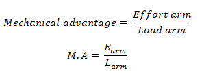
Mechanical Advantage
Mechanical advantage (M.A) is the ratio of load and effort
Mathematically:
-

Mechanical advantage has no SI unit.
Example 1
Example 1
A simple machine raises a load of 100N by using a force 50N. Calculate the mechanical advantage.
Solution;
-

Example 2
Example 2.
A force of 20N raises a load of 100kg. Calculate mechanical advantage of the machine.
Solution
-

img4

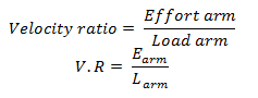
Velocity ratio
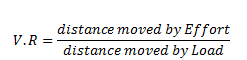
Velocity ratio is the ratio of distance travelled by effort and distance travelled by load. Or Velocity ratio is the distance moved by effort per distance moved by load.
-

Example 3
Example
In a certain machine a force of 10N moves down a distance of 5cm in order to raise a load of 100N through a height of 0.5cm calculated the velocity ratio (V.R) of the machine.
Solution:
Distance by Effort = 5cm
Distance moved by load = 0.5cm.
From
-

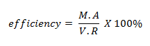
Efficiency of Machine
Efficiency of machine is the ratio of work output and work input.
Work output = Load x Distance moved by Load
Work input = Effort x Distance moved by Effort
-

A perfect machine has 100% Efficiency. Therefore M.A is equal to V.R.
Note: most machines are imperfect machines since efficiency is less than 100% this is due to the friction and heat and loss of energy.
Example 4
Example1:
A certain machine with force of 10N moves down a distance of 5cm in order to raise a load of 100N through a height of 0.5cm.
Calculate:
- M.A
- V.R
- Efficiency of machine
Solution:
Date given:
Effort = 10N
Load = 100N
Distance moved by effort = 5cm
Distance of load= 0.5cm
Efficiency machine?
Efficiency of machine () = M.A x 100%
-

Different Kinds of Simple Machine
Identify the different kinds of simple machines
Different Kinds of Simple Machines
Types of Simple Machines
- LEVERS
- PULLEYS
- INCLINED PLANE
- THE SCREW AND SCREW JACK
- WHEEL AND AXLE
- HYDRAULIC PRESS
A lever is a rigid body, which when used turns about a fixed point called a fulcrum or pivot. It is used to shift heavy loads.
The Three Classes of Levers
Identify the three classes of levers
Classes of Levers
There are three classes of levers:
- First class lever
- Second class lever
- Third class lever
First Class Lever
Is the class lever whereby the pivot is between load and effort. Examples of first class levers are: see-saw, crowbar, pair of scissors and claw hammer.
First Class Lever

Second Class Lever
Is the class lever where by load is between pivot and load. eg, wheel barrow, tongs, nutcracker, bottle opener.
Second Class Lever

Third Class Lever
Is the class lever whereby Effort is between load and pivot. Eg, fishing load.
Third Class Lever

The Mechanical Advantage, Velocity Ratio and Efficiency of Lever
Determine the mechanical advantage, velocity ratio and efficiency of lever
Mechanical Advantage of a Lever
The effort arm is the distance from the effort to the fulcrum and the load arm is the distance from the load from the fulcrum.
Velocity Ratio of a Lever
Efficiency of a Lever
Levers in Daily Life
Use of levers in daily life
The reason for a lever is that you can use it for a mechanical advantage in lifting heavy loads, moving things a greater distance or increasing the speed of an object.
- Increase force:You can increase the applied force in order to lift heavier loads.
- Increase distance moved
- Increase speed: You can increase the speed that the load moves with Class 1 or Class 3 levers.
A pulley is a grooved wheel, which is free to turn about an axle that is fixed in a frame.
Different Pulley System
Identify different pulley systems
Types of Pulleys
- Single fixed pulley
- Single movable pulley
- The block and tackle system of pulley
Single fixed pulley
This is the type of pulley whereby effort is applied at one end of the tape in order to raise the load. Single fixed pulleys are used to raise small objects e.g. Flags. Consider the diagram below:-
Single fixed Pulley

M.A and V.R of single fixed pulley

Single Movable Pulley
Single movable pulley is the one which load is multiple of Effort.
Load = 2E
Consider the following diagram
Single movable pulley

M.A and V.R of single movable pulley

The block and tackle system of pulley
When two or more pulleys are fixed in a frame, a block is formed. The pulleys in each block are fixed independently on separate axles. Consider the diagram below:-
Block and tackle system of pulley

Note; mechanical advantage = Load/Effort
Velocity ratio of Block and tackle system is equal to the number of pulleys.
Example 5
Example 1
A block and tackle pulley system has a velocity ratio of 4. If a load of 200N is raised by using a force of 75N. Calculate the mechanical (i) Advantage of the system (ii) efficiency of the system.
Solution;
Data given
Velocity ratio (V.R) = 4
Load = 200N
Effort = 75N
M.A =?
M.A and Efficiency of block and tackle pulley system

Mechanical Advantage, Velocity Ratio and Efficiency of Pulley System
Determine mechanical advantage, velocity ratio and efficiency of pulley system
Mechanical Advantage of a Pulley system (Block and Tackle)
A block and tackle pulley system is a machine which has a single rope which passes around the pulleys that are in two blocks. We can find the mechanical advantage of a block and tackle pulley system by counting the number of ropes that support the lower block.
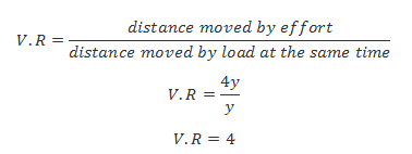
Velocity Ratio of Block and tackle system
When the lower two pulleys move up a vertical distance y, corresponding to movement y of the load L, each pulley releases a length y of the rope on each side giving a total length 2y.
With all this movement of pulleys, the effort E is moved down a distance of 2 x 2y or 4y. Thus,
Efficiency of a Block and Tackle
For a perfect block and tackle system,efficiency is 100% because the M.A and V.R are all equal to number of pulleys or number of ropes holding the lower block.However, the block and tackle system of pulleys suffers from frictional forces which reduces its efficiency by making M.A smaller than V.R. For that matter, efficiency of a block and tackle system is obtained as;
Pulley in Daily Life
Use of pulley in daily life
Uses of Pulleys
Pulleys have been used for lifting for thousands of years. The most prevalent and oldest example are their uses on ships and boats. The block and tackle have been a key tool for raising sails and cargo. Another major use for pulleys is with cranes.
Pulleys have been used also in modern times with various machines and systems. Even in the space age, pulleys have been an important aspect for the construction and operations of spacecraft and aircraft. It is with a pulley system that rudders for an aircraft are controlled.
Pulleys are used in everyday life, from vehicles to moving equipment such as cranes.
The Concept of Inclined Plane
State the concept of inclined plane
An inclined plane is a sloping plane surface, usually a wooden plank used to raise heavy load by pulling or pushing them along the surface of the plane.
An inclined plane

Mechanical Advantage, Velocity Ratio and Efficiency of Inclined Plane
Determine mechanical advantage, velocity ratio and efficiency of inclined plane
Mechanical advantage of the inclined plane
The M.A of inclined plane is obtained as the ratio of the Load to Effort.

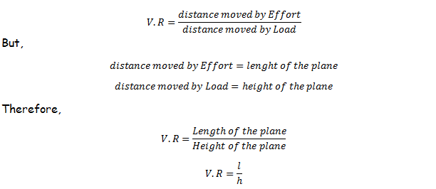
Velocity Ratio of Inclined Plane
The V.R of inclined plane is obtained as the ratio of the distance moved by Effort to the distance moved by the Load. But, in inclined plane, the load moves a distance equal to the height of the inclined plane. The effort moves the distance equal to the length of the plane. Therefore, V.R of the Inclined Plane is obtained as follows;
Efficiency of Inclined Plane
Inclined Plane in Daily Life
Apply inclined plane in daily life
Application of Inclined Plane
Inclined planes are widely used in the form of loading ramps to load and unload goods on trucks, ships, and planes.Wheelchair ramps are used to allow people in wheelchairs to get over vertical obstacles without exceeding their strength. Escalators and slanted conveyor belts are also forms of inclined plane.
In a funicular or cable railway a railroad car is pulled up a steep inclined plane using cables. Inclined planes also allow heavy fragile objects, including humans, to be safely lowered down a vertical distance by using the normal force of the plane to reduce the gravitational force. Aircraft evacuation slides allow people to rapidly and safely reach the ground from the height of a passenger airliner.
The Structure of a Screw Jack
Describe the structure of a Screw Jack
Structure of Screw Jack
A screw Jack consist of a cylinder with a spiral ridge runs round it. The spiral is called the thread (T) and the distance between two adjacent threads is called the pitch (p) of the screw.
Consider the following diagram.
The bolt and screw

The Screw Jack

The Mechanical Advantage, Velocity Ratio and Efficiency of a Screw Jack
Determine the mechanical advantage, velocity ratio and efficiency of a Screw Jack
Mechanical advantage of the screw jack
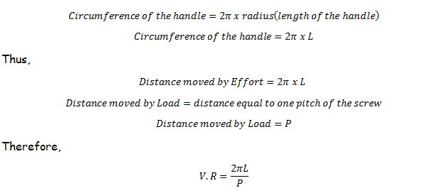
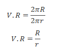
Velocity Ratio of the Screw Jack
The V.R is obtained as,

When the handle of the screw jack is turned around one cycle the load is lifted a distance equal to one pitch, P. in this case the Effort moves a distance equal to the circumference covered when the handle was turned.
Efficiency of Screw Jack
Example 6
Example 1
A screw jack with a pitch of 0.2cm and a handle of length 50cm is used to lift a car of weight 1.2 x 10⁴N. If the efficiency of the screw is 30%, find:
- The velocity ratio and mechanical Advantage of the machine
- The effort required to raise the car
Solution;
Date given
Pitch = 0.2cm
Radius= 50cm
Load = 1.2 x10⁴N
Efficiency of jack =30%
V.R=?
M.A=?
Effort+?
-

The Screw Jack in Daily Life
Use the Screw Jack in daily life
Screw jacks are used to lift heavy loads despite the large friction they produce. The heavier the load the higher the friction force. They are self-locking, meaning that when the applied force is removed, they do not rotate backwards. They are used in adjusting workplace chairs and tables. They also help in pulling and pushing machine equipment as well as tightening mechanical parts.
The Structure of a Wheel and Axle
Describe the structure of a wheel and axle
Structure of Wheel and Axle
A wheel and axle is a simple machine that consists of a wheel and axle mounted with the same axis of rotation. The radius of the wheel is always greater than that of the axle.
Consider the diagram below:
Wheel and Axle

The Mechanical Advantage, Velocity Ratio and Efficiency of a Wheel and Axle
Determine the mechanical advantage, velocity ratio and efficiency of a wheel and axle
Mechanical advantage of Wheel and Axle
The M.A of inclined plane is obtained as the ratio of the Load to Effort.
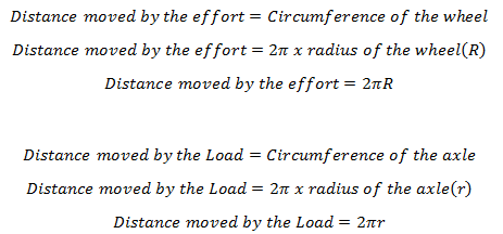
Velocity Ratio of Wheel and Axle
The wheel and axle work in a way that, when an effort is applied to rotate the wheel, the axle which pulls the load is simultaneously rotated covering same number of rotations as those of the wheel.
In one rotation the wheel moves the effort a distance equal to its circumference. Similarly, the axle moves the Load up a distance equal to its circumference. That means,
Since,
Then, for wheel and axle,
Efficiency
The Wheel and Axle in Daily Life
Use the wheel and axle in daily life
Application of Wheel and Axle
Wheels help people do work in two ways. First, like levers or inclined planes, wheels allow you to do something easy for a longer time, instead of doing something hard for a shorter time. If you turn a large wheel fixed to an axle, the axle will also turn. You can turn the large wheel easily (but it takes a lot of turning to go all the way around).
The axle will go around a much shorter distance, but with more force. So you can use a wheel to create a mechanical advantage - you can turn something heavy, by spinning a large wheel attached to an axle that is attached to the heavy thing.
That's how a pencil sharpener works. Or, you can do it the other way around - use a lot of force to turn the axle, and that will spin the wheels really fast. That's what cars do.Wheels are the most important part of pottery wheels, wagons and cars, but also ofwheelbarrows,spinning wheels, water wheels, windmills, andpulleys.
Also, wheels on a wagon only touch the ground at one spot at a time, keeping the rest of the wagon off the ground. This makes less friction, so that the wagon is easier to move than if you were pulling it along like a sled.
The Structure of Hydraulic Press
Describe the structure of Hydraulic Press
A hydraulic press is a machine that is used generate compression force that can be used to crush, straighten or mould objects. It has two sides one on which effort is applies and the other on which the load is placed.
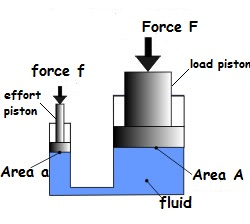
Force f is applied on the effort piston and transmitted in form of pressure within the fluid to the area of the load piston. There it is converted into large force F which can do tremendous kind of works.
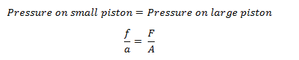
The pressure created by the effort piston is all transmitted without loss to the load piston. That is,
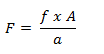
The force obtained in the load piston is larger and can do great amount of work. The force is large due to the fact that the area A of load piston is larger compared to area a of smaller piston. This large force F can be obtained by making F subject from the above formula,
That is the reason for using hydraulic press in heavy duty works.
Mechanical Advantage, Velocity Ratio and Efficiency of a Hydraulic Press
Determine mechanical advantage, velocity ratio and efficiency of a Hydraulic Press
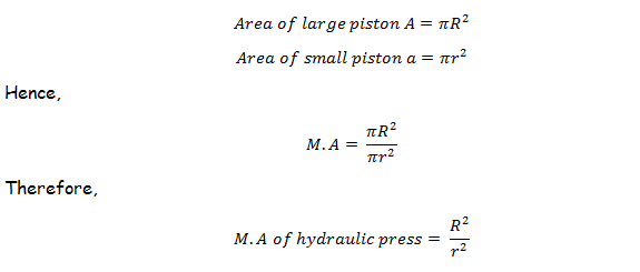
Mechanical Advantage
In hydraulic press small force (Effort) applied on the small piston is used to overcome a much greater force (Load) on the large piston. That means, effort E is that small force f applied on the effort piston and load L is that large force F on the load piston.
Since,
It comes that,

But from the formula,
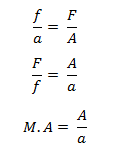
It is known that,
Velocity Ratio
Suppose a small effort (E) is applied downwards on the effort piston of radius (r) which moves downward through a distance x to lift the load piston of radius (R) carrying the load (L) through the distance y. as shown in the diagram below;
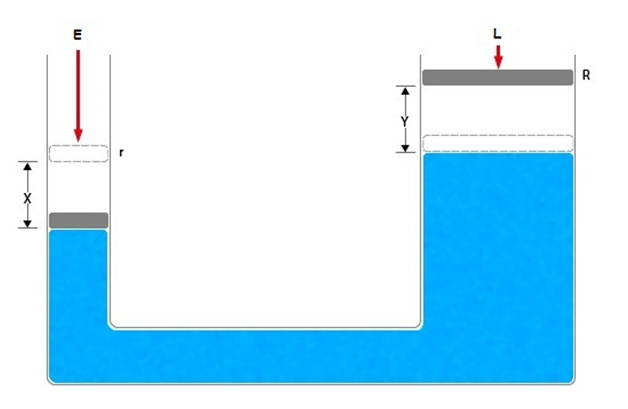
If we neglect friction forces, the work done by the effort piston is equal to the work done by the load piston.
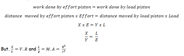
Therefore,
Efficiency
The efficiency of the hydraulic press can never be 100% and can be calculated by,
The Hydraulic Press in Daily Life
Use the Hydraulic Press in daily life
Uses of a Hydraulic Press
A hydraulic press is used for almost all industrial purposes. But basically it is used for transforming metallic objects into sheets of metal. In other industries, it is used for the thinning of glass, making powders in case of the cosmetic industry and for forming the tablets for medical use. The other common uses of the hydraulic presses are as follows:
For crushing cars
A hydraulic press is the heart of any car crushing system. In this process, a hydraulic motor applies a large pressure on the fluids into the cylinders. The fluid pressure makes the plates rise and with a large force, the plate is driven on the car thereby crushing it.
Fat-free cocoa powder
While processing the cocoa beans, a liquid known as chocolate liquor is derived. For making fat-free cocoa powder, this liquid is squeezed out in a hydraulic press. After this stage, this liquid is processed further to make a powder. The powder thus derived is cocoa powder, which is fat-free.
For sword making
In the process of making swords, a hydraulic press is used to give a flat shape to the raw steel.

can u send for me this
ReplyDeletenotice
Who are you?
Delete